Common EFI Sensors: What, Where, Why?
Published on: June 28, 2024Categories: Education
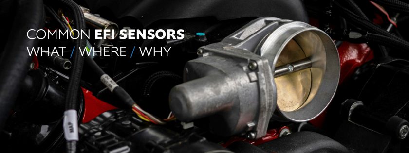
Electronic Fuel Injection (EFI) systems are crucial for the efficient operation of modern engines, ensuring optimal performance and fuel economy. At the heart of these systems are various sensors that provide the Engine Control Unit (ECU) with vital data to manage the engine’s functions. This article will delve into the most common EFI sensors, explaining their purpose, operation, and significance.
Crankshaft and Camshaft Sensors
Crankshaft Sensor:
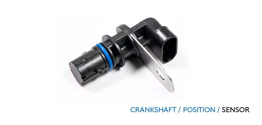
The crankshaft sensor is essential for translating engine rotation and speed into data that the ECU can use to calculate spark timing and other critical parameters. It works by detecting the teeth of a crank trigger wheel attached to the crankshaft. As the teeth pass by the sensor, it generates signals corresponding to the engine’s rotational position and speed.
There are two main types of crankshaft sensors:
Hall Effect Sensors: These generate a digital signal (square wave) and are known for their accuracy and reliability in high-performance applications.
Variable Reluctance (VR) Sensors: These generate an analog signal (sine wave) and are valued for their robustness and reliability.
Camshaft Sensor:
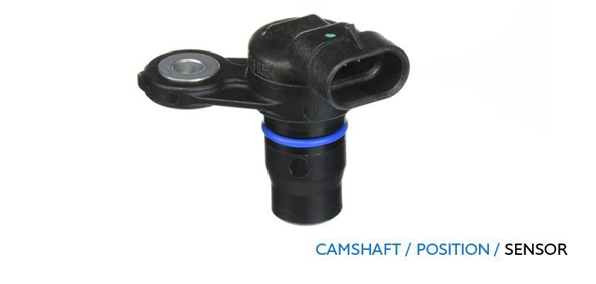
Similar to the crankshaft sensor, the camshaft sensor helps determine the exact position of the camshaft. This is vital for sequential fuel injection and ignition. The camshaft sensor ensures that fuel is injected at the optimal time, corresponding to the valve’s position.
Manifold Air Pressure (MAP) Sensor
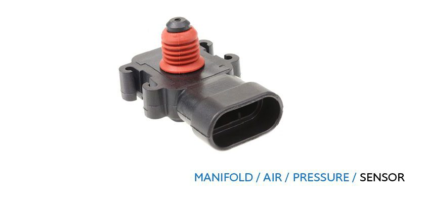
The MAP sensor measures the vacuum and pressure inside the intake manifold, providing data on engine load. This information helps the ECU determine the optimal air-fuel mixture. The sensor operates on a 0-5V scale, with different versions (1-bar, 2-bar, etc.) suitable for naturally aspirated or boosted engines. For example, a 1-bar sensor is used for naturally aspirated engines, while higher bar sensors are used for turbocharged or supercharged engines.
Throttle Position Sensor (TPS)
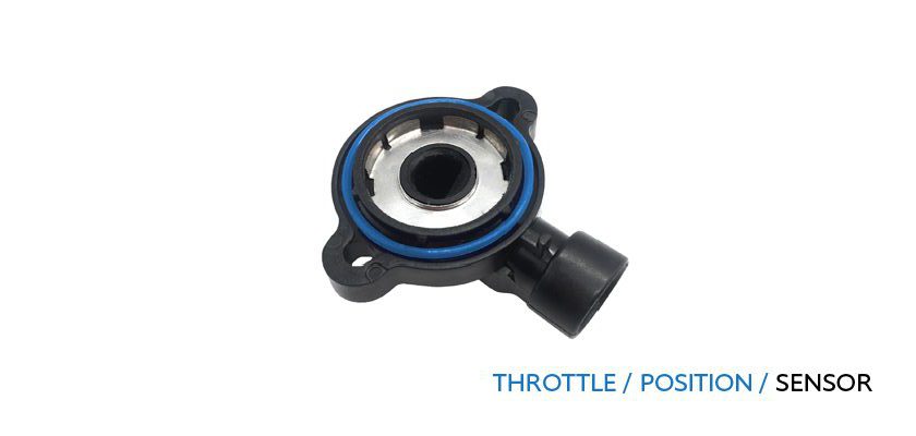
The TPS measures the position of the throttle plate, which controls the amount of air entering the engine. This sensor helps the ECU manage fuel injection and ignition timing based on throttle input. It is a variable resistance sensor that sends a 0-5V signal to the ECU, indicating the throttle’s position from fully closed to fully open.
Intake Air Temperature (IAT) Sensor
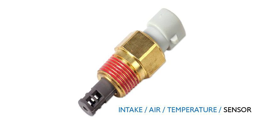
The IAT sensor measures the temperature of the air entering the engine. This data is crucial for calculating air density and ensuring the correct air-fuel mixture. There are two types of IAT sensors:
Open Tip Sensors: Offer faster response times and are preferable in performance applications.
Closed Tip Sensors: Provide slower response times and are typically used in standard applications.
Coolant Temperature Sensor
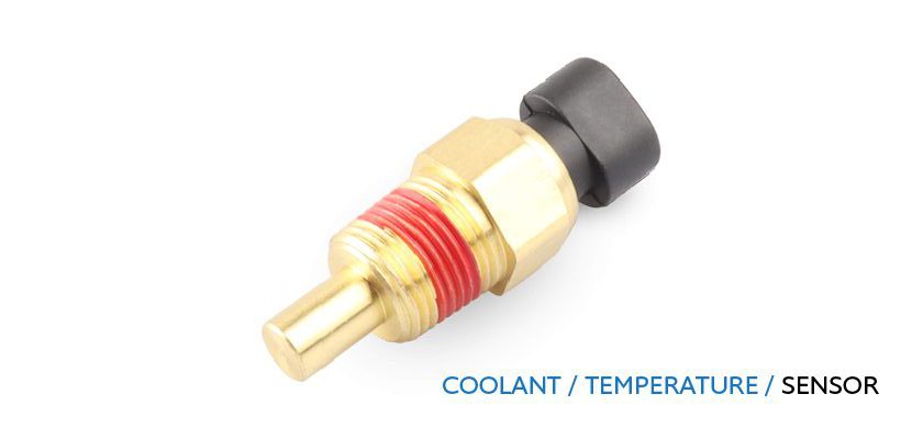
This sensor measures the engine’s coolant temperature, providing data for various functions such as activating the radiator fan and adjusting fuel delivery for optimal engine temperature. It operates similarly to the IAT sensor, using a variable resistance design.
Mass Air Flow (MAF) Sensor
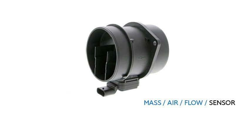
The MAF sensor measures the mass of air entering the engine, which is essential for accurate fuel delivery and ignition timing. It is particularly important in OEM applications, where it ensures precise air-fuel calculations. MAF sensors come in different scales and need to be calibrated based on the specific engine’s air intake characteristics.
Oxygen (O2) Sensors
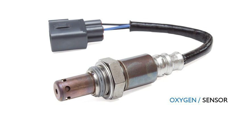
Narrowband O2 Sensors:
These sensors measure the oxygen content in the exhaust gases, primarily used to maintain stoichiometric air-fuel ratios during idle and part-throttle conditions. They operate within a narrow range and provide a 0-1V signal to the ECU.
Wideband O2 Sensors:
These provide a broader range of measurements (typically from 10:1 to 20:1 air-fuel ratio) and are used for more precise fuel management, especially under varying load conditions. They output a 0-5V signal, allowing the ECU to make more accurate adjustments.
Knock Sensor
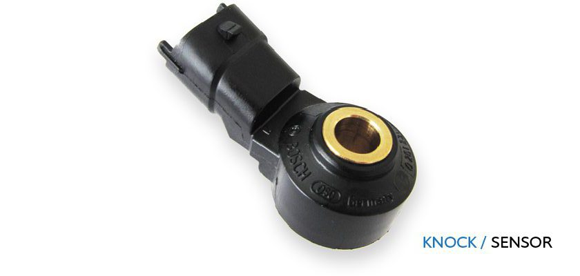
The knock sensor detects engine knocking or pinging, a condition that can cause severe engine damage. It works by sensing the vibrations caused by knocking and sending a signal to the ECU, which then adjusts the ignition timing to prevent further knocking. The sensor is typically mounted on the engine block and uses a piezoelectric element to detect knock events.
Conclusion
Understanding these EFI sensors and their roles is crucial for anyone involved in automotive tuning or maintenance. These sensors work together to ensure that the engine operates efficiently, delivering the right amount of fuel and spark at the right time. For enthusiasts and professionals using HP Tuners products, a deep knowledge of these sensors can enhance tuning precision and vehicle performance.
Stay tuned for more detailed explorations of EFI systems and tips. Happy tuning!

