
DTC P0328 - Knock Bank 1 Sensor Circuit High
Conditions for setting dtc P0328
| ■ | Engine Running |
| ■ | Knock Bank 1 Sensor ≥ 4.9 volts |
| ■ | The above must be present for a period of 128 instances/cycles or greater to trigger DTC P0328 |
|
Step |
Action |
Value (s) |
YES |
NO |
|
1 |
- Key on, Engine running - Within VCM Live, open the knock sensor DTC parameter, does the knock sensor parameter display 4.9 volts or higher? |
≥ 4.9 volts |
Go to Step 2 |
Intermittent Issue (Refer to Intermittent Diagnostics) |
|
2 |
- Key OFF - Disconnect the Knock 1 sensor connector and the ECU harness connector "D" - Using a DVOM check for continuity between the Knock 1 sensor signal 1 cavity "A" (for both Drive-By-Cable & Drive-By-Wire harnesses) & the ECU connector "D" pin 1 (for both Drive-By-Cable & Drive-By-Wire harnesses) - Do you have continuity between them? |
|
Go to Step 3 |
Repair the circuit as necessary, locate any wires that need to be repaired or replaced |
|
3 |
- Key OFF - Disconnect the Knock 1 sensor connector and the ECU harness connector "D" - Using a DVOM check for continuity between the Knock 1 sensor signal 2 cavity "B" (for Drive-By-Cable harness) cavity "B" is the low reference signal (for drive-By-Wire) & the ECU connector "D" pin 8 (for both Drive-By-Cable harness) & C19-B(for Drive-By-Wire harness) - Do you have continuity between them? |
|
Go to Step 4 |
Repair the circuit as necessary, locate any wires that need to be repaired or replaced |
|
4 |
- Replace Knock 1 sensor - Is the replacement complete? |
|
Go to Step 5 |
N/A |
|
5 |
- Clear any DTC from the ECU - Turn the ignition off and wait 30 seconds - Start the engine and operate the engine to full operating temperature - Observe the Check Engine Light on the Menu bar in VCM Live - After operating the engine within the test parameters, check for any store codes - Does the engine operate without any stored DTC's? |
|
System is now operational and ready to be tuned |
Contact HP Tuners Support |
Table 20. Knock Bank 1 Sensor Circuit High Diagnostics Table
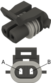
Figure 8. Drive-By-Cable Knock 1 Sensor Cavity Connector Location
_137x252.png)
Figure 9. Drive-By-Wire Knock 1 Sensor Cavity Connector Location
