
Hey guys any consensus on the best size straightener to use, specifically for a 100mm maf on an f-body style intake tract (very limited length section of straight pipe).


Hey guys any consensus on the best size straightener to use, specifically for a 100mm maf on an f-body style intake tract (very limited length section of straight pipe).
Last edited by spy2520; 07-10-2012 at 12:25 PM.
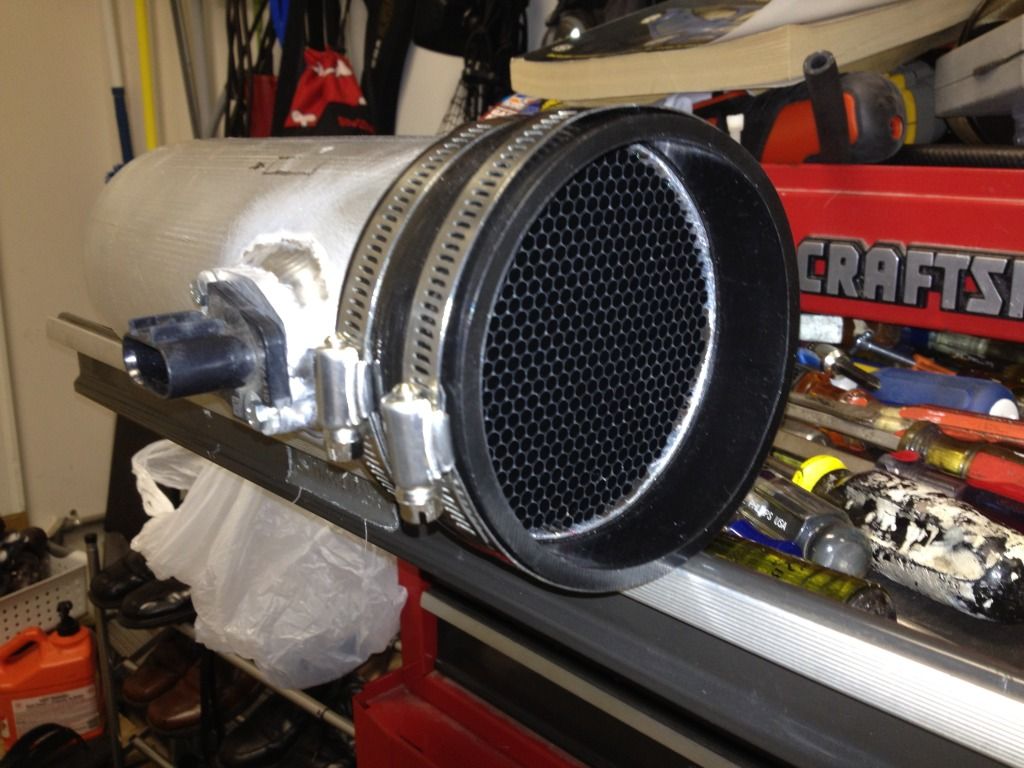
I have a 4" slot style maf with plastic honeycomb about 3/4 " in front of the maf. Was wondering if anyone else has this maf/honeycomb combo and could share a transfer function to help get me started for when I first fire this thing up. I am very much starting from scratch here. This is on a custom eaton supercharged chevy trailblazer with a 4.2L in line 6! Thanks
I just ordered the 6:1 alum screen for my blow through setup in 35" pipe. One thing I havn't seen addressed is the optimal distance between the MAF sensor and the screen. TRE or treadstone also sells these honeycomb screens and they say not closer than 2" from the sensor.
I'd say consider factory honeycombs as a benchmark. All the ones I have seen are pretty close to the sensor.
I have been following thread for different application. Look s like you guys are breaking new ground. Although, as another poster mentioned, you are WAY ABOVE my head. I can see what you are doing, and have an interest.
My application for the honeycomb diffuser is a 2002 Porsche Boxster S, approx. 375 RWHP, up from 350 stock - again, waaaay below you guys! My question is for a 3" intake application or approx. 73MM cold air intake and Throttle Body of same diameter.
Not sure what all you need to determine honeycomb size for my application. Do NOT have access to all the Durametric info, still a NEWB.
I have a couple ????s:
1). How far from the MAF do you place the Honeycomb for a 3" intake?
2). Porsche placed the MAF about 2 feet from Throttle Body, should I relocate it closer as I have seen in your applications.
3). The Intake has several bends in it, would I need more than one honeycomb to straighten airflow or should I place it just downstream from airbox where the air flow "starts" to help it "bend" the air easier to the TB? Which is the BETTER application of honeycomb filter?
4). Would I better served getting a 4" intake and "stepping down" to 3" TB, in which case - where would the MAF/Honeycomb be placed?
I KNOW this is NOT your choice of cars to tune but IT IS REALLY fun to drive around a race track (the twisty kind)! We are trying to get there, ironically it is SLOWLY coming together.
I will yield to your experience!
Thanks in advance!
Mark
a.k.a. Homeboy981 - because I buy homes….used to buy a lot more, but since Congress passed so many #$$^ laws against Owner Financing…it is FORCING everyone to use banks. I have found PEOPLE, not banks, IS A FAR BETTER SOLUTION! How long would it take to absorb excess inventory? We were buying 20+ homes per MONTH! There used to be AT LEAST 10 other people buying in that quantity. Now, we are lucky IF 10 people like me are still in business! BTW, I used to be over $1 Million in net worth - trust me, it DOES NOT guarantee your future! I went from a million to one in less than 4 years!
Here's a pic of the car and a drawing of the proposed intake…before I found this thread!
Seems like different rigs need different placement. If a ratio change does not help then adjusting the spacing can help. Some folks have some pretty sophisticated metering for the application to judge results.
Installed the plastic version about 1" away same as stock MAF, car runs nice didn't even need to update the MAF table from stock, using A&A 4" long pipe.
Issue using aluminum screen is with the A&A one piece pipe you have to push the screen into the pipe about a foot, by time it gets there it doesn't look pretty anymore.
The plastic one compresses and tries to expand out putting constant pressure inside so didn't need any adhesives, love it!
But yes if I had a pipe where the screen would just mount in the beginning, then i'd use aluminum.
TTT
Anyone know where to get the correct Maf table for a 100mm MAF?
I can't locate it on the LPE site currently, but I previously downloaded the attached from their site.Originally Posted by silverzz28

Thanks! Car loved it
That file is flawed somewhat. I talked to them several times and never really got anywhere. The file you are looking at is for a the MAF transfer function only, that part of it is fine and is a good starting point. However the IAT transfer function is missing from it. The C5 reads in a/d counts and the C6 reads in ohms, that is on the PCM, but the IAT sensor itself is different and they are not linear. You can have a temp that is about 5 degrees different to over 40 degrees difference. The biggest issue it the furthest spread is around the 100F mark which is what the intake temp is most of the time. Do an sanity check and see what your IAT temp is compared to the ambient air before you start the car up in the morning, you will see what I am talking about. The IAT effects everything in the calibration and it needs to be right.
http://www.powrmax.com/PowrMAF100%20Tables.html
Bill Winters
Former owner/builder/tuner of the FarmVette
Out of the LSx tuning game
Mine is about 20 degrees off. How do I change it?
Go to your IAT sensor calibration table which is under the engine diag> menu, then subtract 12 degrees from the whole table. should put you at ambient.
How would that work when the meters are not linear. They also do not follow the same curve. As I stated earlier, the correct way to do it is to take the correct ohm reading, convert it to voltage and then to the a/d counts. Then it is correct at every axis point.
I spent a several hours writing a spread sheet to do it. If you know the formula's you can do it in excel.
This worked for me it appears. Was the same before start up and car stayed at temp cruising down the road.(Ram air) intake.
maybe your tables read diffrent im on the E40PCM so the tables were already similar, i searched and found a thread about subtracting values to get to where you need to be and the solution worked for me.
If you have an E40 there is no reason why you should not have the correct IAT transfer in there, your E40 is reading ohms. The axis is the same for a car with a Hitachi, as easy as copy and paste. The LS1B ecu is a different story, OHms is not on the axis, A/D counts are. The two sensors for one are not linear, two the curve is different between the two. You can't subtract one number for all of them. You may have subtracted the correct number at your operating IAT temps, but as the weather changes the numbers will start to get further apart. There is not easy trick for this, but it is also not hard to put the correct data in the x function and make it work correctly at all points.
Let me explain it like this, the way you are doing it is not exactly wrong, but it is also not right. You could take temps at different points and do a sanity test, example my IAT temp says 90 degrees but its 70 ambient. So this would be a 20 degree difference that you could change in the box. But when you start the car you do not know how much temp is changing from the heat effect of the intake. So you would have to do sanity tests at all those different temps from -40 through 284 in order to make your curve correct. So you say you don't need them, well I live in VA and I have a temp spread between 25 degrees and 100+ degree during the year. It makes a huge difference, the IAT temp is used in calculating fuel so it really needs to be spot on. The easier way would be for you to find a file for a LS3 or LS7 and copy the IAT transfer function and past it into your E40 and your done. The LS1B ecu is not as easy but just as important for it to be done correctly.

 Reply With Quote
