Page 8 of 11 FirstFirst ... 4567891011 LastLast
Results 141 to 160 of 206

Thread: Timing Blips, Shudders at Speed... Caused by What?

  1. #141
    Senior Tuner edcmat-l1's Avatar
    Join Date
    Aug 2006
    Location
    5BA8
    Posts
    3,253
    Put a catch can on it. All LS engines can benefit from an oil separator in the PCV system. Run some seafoam through the intake. Put some NGK 4177s in it. At 9.5:1 compression you should not have ANY spark knock with the timing you guys got in it. It should NEED 26-28 degrees to make any power. Might take more. This is where either a dyno or just extensive experience comes into play. Without a dyno ya just put the timing where it needs to be and back the sensors down until they aren't going off like jingle bells.

    I don't have a lot of faith in the GEN3 knock sensor system anyway.

    EFI specialist
    Advanced diagnostics, tuning, emissions
    HPtuners dealer and tech support
    email=[email protected]

  2. #142
    Senior Tuner
    Join Date
    Mar 2022
    Location
    Indiana
    Posts
    2,939
    Decent job on the High spark table. I still would've preferred the TIP In settings. That was a safe value I gave you. It's the global gains that can get you into trouble.

    edcmat-l1 is right about the questionable accuracy of the knock sensors, especially if they haven't been changed recently. I don't like the idea of whoring for 26-28 with dished pistons in a truck/suv. If 22 degrees WOT and still no KR then stop. Personally I'd shoot for 18 WOT and call it.

    Nice thing is you've learned enough and have the tools to make changes as you see fit.

  3. #143
    Senior Tuner
    Join Date
    Mar 2022
    Location
    Indiana
    Posts
    2,939
    Because the KR occurs when the throttle is stabbed that means it's likely detonation. The sudden transient causes a brief moment of uneven charge distribution among and within cylinders, resulting in combustion instability. If KR was related to spark plugs then that would be pre-ignition, and KR would be seen throughout, increasing in intensity with duration of load.

    One thing to try is decrease the rate of flame propagation and reduce lean spots within the cylinder by dousing it with fuel. Set PE where TIP In KR has been present like this:
    PE_det.png

    Or maybe more like this:
    PE_det_2.png
    Last edited by SiriusC1024; 12-08-2023 at 08:00 PM.

  4. #144
    Tuner
    Join Date
    Nov 2022
    Location
    Dallas, TX
    Posts
    72
    Quote Originally Posted by SiriusC1024 View Post
    Decent job on the High spark table. I still would've preferred the TIP In settings. That was a safe value I gave you. It's the global gains that can get you into trouble.
    ...
    Nice thing is you've learned enough and have the tools to make changes as you see fit.
    Definitely took me a minute to get the hang of it. Working the tune myself between your edits (like homework) definitely helped. I could kinda iterate and try different stuff to see how close I could get to your changes on the MAF and SD tunes. Anyways. Very helpful having all those iterations and your explanations.

    KR tables for first and second logs:
    IMG_20231208_200547.pngIMG_20231208_200549.png

    ...and high octane spark tables for each, respectively:
    IMG_20231208_200625.jpgIMG_20231208_200630.jpg

    Quote Originally Posted by SiriusC1024 View Post
    edcmat-l1 is right about the questionable accuracy of the knock sensors, especially if they haven't been changed recently. I don't like the idea of whoring for 26-28 with dished pistons in a truck/suv. If 22 degrees WOT and still no KR then stop. Personally I'd shoot for 18 WOT and call it.
    So... thoughts about this. Knock sensors are new, swapped new ones into it when I swapped the 6.0 into the truck. I figured I would thank myself for it some day.

    I did one more iteration of the high-octane timing table using a MAP/RPM table to mod KR. I figured I can aim to establish a timing baseline of <1% KR everywhere and see where that puts me timing wise. Then maybe dial the knock sensor gains back somehow (edcmat-l1 referenced the C5 Vette table?) and slowly increase spark a couple degrees at a time to find knock and dial it back slightly from there. Another approach might be to just bring the table up to 18% and then adjust knock sensitivity to tolerate it. Are either of those acceptable approaches?

    I am open to suggestions, obviously. ��
    Last edited by squeeler642; 12-08-2023 at 08:45 PM.
    2003 Tahoe Z71 - ATK HP93/LQ4 6.0L swap, stock 4L60E (for now), headers, e-fan conversion, and warm air intake on 33" ATs.

  5. #145
    Senior Tuner kingtal0n's Avatar
    Join Date
    Feb 2017
    Location
    miami
    Posts
    1,799
    Never use a catch can. Catch cans are for broken engines.
    https://www.corvetteforum.com/forums...post1605398320

    Instead, measure the crankcase pressure
    https://www.supraforums.com/threads/...#post-13980010

  6. #146
    Senior Tuner
    Join Date
    Mar 2022
    Location
    Indiana
    Posts
    2,939
    The approach I'd take is re-run tune DynAir_1. Apply the second PE setting I suggested.

    If KR is still present increment up the TIP In sensitivity until knock disappears. If you exceed the values of 14 and 13 for them then bring down spark.

    As far as LQ4 vs Corvette knock sensor settings think about it. What's cast iron sound like when you tap it with a hammer? And aluminum? How about a solid piece vs hollow?

    6.0 LQ4 is a cast iron block with larger bore diameters than the 5.7 aluminum block. They use the same sensor. The settings are tuned to the frequencies of each. The Silverado settings are for extreme reliability with enough factor of safety to be good for heavy duty applications in all possible driving conditions.

    And yes installing a catch can at some point would be a pragmatic thing to do.

  7. #147
    Senior Tuner
    Join Date
    Mar 2022
    Location
    Indiana
    Posts
    2,939
    Pay attention, though. There's a difference between KR and the actual knock event. Knock happens then triggers KR. KR decreases according to the decay rate. Just because KR is showing in all those cells doesn't mean all those spark settings are causing knock. Look at what's happening on the graph. Don't adjust the timing in all KR zones.

    That's what I'm trying to explain to you about TIP In. That's what is triggering knock here. Knock Retard is sustained due to the decay rate. The thing to address is TIP In conditions and knock sensitivity.

  8. #148
    Tuner
    Join Date
    Nov 2022
    Location
    Dallas, TX
    Posts
    72
    Long post... questions in bold.

    Maybe a stupid question, but what is the ultimate consequence of running a tune that has to correct for knock regularly?

    Quote Originally Posted by SiriusC1024 View Post
    That's actually looking a lot like Burst Retard. Since that's disabled it's real. Notice how KR occurs with a rapid throttle transition.

    Instead of adjusting the Main tables, I would try increasing the Knock Sensor Level vs Tip In TPS table to 14 across, 13 for Tip In RPM, and see what that does for you.
    Is "tip in" regarding knock sensors just referring to act of varying the knock sensor sensitivity as a function of different variables? Might just be my inability to search the forum properly but it's hard to find info on this I feel.

    How do we know that knock is real and not an overly sensitive sensor calibration? Is there away for us to know that?


    Jumping back to this post for a sec. Went ahead and switched the high octane spark table to your original from the Dyn_1 tune revision. Figured I might as well try these changes you recommended. Just wanting to make sure I have these tables set up right.

    Knock Sensor Level vs Tip In TPS (table): Attachment 140563
    Knock Sensor Level vs Tip In RPM (table): Attachment 140565

    Quote Originally Posted by SiriusC1024 View Post
    Pay attention, though. There's a difference between KR and the actual knock event. Knock happens then triggers KR. KR decreases according to the decay rate. Just because KR is showing in all those cells doesn't mean all those spark settings are causing knock. Look at what's happening on the graph. Don't adjust the timing in all KR zones.

    That's what I'm trying to explain to you about TIP In. That's what is triggering knock here. Knock Retard is sustained due to the decay rate. The thing to address is TIP In conditions and knock sensitivity.
    Glad you mentioned the cells where KR is triggered vs. the cells that are affected by KR on the decay. Would you just target the cells with the highest values, clearly the worst offenders?

    Quote Originally Posted by SiriusC1024 View Post
    6.0 LQ4 is a cast iron block with larger bore diameters than the 5.7 aluminum block. They use the same sensor. The settings are tuned to the frequencies of each. The Silverado settings are for extreme reliability with enough factor of safety to be good for heavy duty applications in all possible driving conditions.

    And yes installing a catch can at some point would be a pragmatic thing to do.
    Heard on the catch can and differences between truck/performance motors. That's totally where my brain went when I saw the initial comment about the Z06 cam. I'm not worried about squeezing every ounce of power out of this motor. Power is cool, but since this is my daily... reliability is cooler. Haha.
    Last edited by squeeler642; 12-08-2023 at 11:08 PM.
    2003 Tahoe Z71 - ATK HP93/LQ4 6.0L swap, stock 4L60E (for now), headers, e-fan conversion, and warm air intake on 33" ATs.

  9. #149
    Senior Tuner kingtal0n's Avatar
    Join Date
    Feb 2017
    Location
    miami
    Posts
    1,799
    Quote Originally Posted by SiriusC1024 View Post
    a pragmatic thing to do.
    I'll do a post for HPtuners forum unlike the others to continue my quest towards keeping people from purchasing unnecessary, detrimental hardware for their engines.


    You will find that it is not a sensible thing to do and that the OEM engineers have already figured the PCV system. They (we can) calculated the mass of oil ejected, you have to when designing an engine and for it's baffle system considerations. Modern vehicles have crankcase pressure sensors to protect engine seals piston rings are engine seals and accumulate oil (which form hard carbon deposits over time and seize the ring destroying the cylinder wall) This is an extremely important topic.
    When crankcase pressure rises combustion gas carries oil from the crankcase and moves up through the piston ring into the combustion chamber (ref: https://www.corvetteforum.com/forums...post1606142803)
    The crankcase must be set to a negative pressure or it will blow oil droplets out from every seal and into every baffle.
    If you do not measure the pressure its the same as installing a fuel regulator without checking or setting the fuel pressure.


    -as the hoses becomes longer (friction) crankcase pressure rises and with it blow-by and oil liquid droplet size/density increase
    -as hoses become larger (volume) crankcase pressure will be higher given some input energy availability
    -as hoses become larger (volume) the rate of change of crankcase pressure is smaller given some input energy duration for wide open throttle
    -cooling combustion gas reduces its average velocity and increases the energy requirement to move blow-by gas because less is supplied by the gas in form the heating
    -as hoses become larger & longer (volume/friction) oil droplet radius and density increases in the blow-by gas


    1. Create an equation predicting mass per unit time (mass/time) of combustion blow-by fluids produced at wide open throttle as a function of piston-wall clearance and crankcase pressure.
    1A. Convert mass/time to volume/time using various temperatures for crankcase gas (a second equation that gives volume of crankcase gas based on temperature).
    With #1 we have mass/time and volume/time blow-by gas equations

    2. With a range of crankcase volumes (include all PCV lines and volumes) dedicated to containing gas as a mixture of combustion products and atmosphere, Determine the energy needed to move a mixture of blow-by combustion fluids contained within the crankcase and piston rings through a 1/4" and 3/8" and 5/8" Hoses/Volume from the crankcase (assume any static constant % of blow-by gas for all comparisons) being evacuated to any PCV pressure supplied by the air filter (or atmospheric pressure (vented) to assume no air filter or a perfect air filter) at varying lengths and frictions of hose and varying total volume.
    With #2 we have energy necessary to organize and move blow-by mass/volume of gas through various hoses at various lengths (friction/volume) and temperature.
    2B. Find available input energy (Head or velocity improver term) based on PCV supplied pressure above, same, and below atmospheric (Vacuum pump and/or Wet sump pressures: 10"Hg, 6"Hg, 2"Hg, Atmospheric pressure 0PSI, and positive crankcase pressure (1psi, 2psi, 3psi) Note: positive pressure adds energy and raises gas density but also increases blow-by, oil droplet radius, and oil droplet density.

    3. Create an equation which will find resulting crankcase pressures with varying crankcase volumes, pipe wall friction(pcv hose length, gas volume and temperature) & blow-by gas mass/time based on energy supplied(pay attention to velocity in the tubes) using PCV applied absolute pressure at wide open throttle given different air filter pressure drop scenarios and pipe surface friction coefficient, do not use an ideal gas equation. Account for the sizes of molecules and use Reynolds for the varying pipe wall friction if possible. Make sure as #1 states to include blow-by as a function of crankcase pressure (more pressure in the crankcase = more blow-by = more mass to evacuate). Be sure to include temperature and it's impact on gas density and volume as it flows through a tube while cooling down at increasing large distances and volumes. You do not have to calculate temperature gradients it is okay to average temperature for the entire crankcase volume because temperature to volume is linear enough. Use temperature to find average velocity (change in x / change in time) of gas to get flow rate at some density. mass flow is equal to density*velocity*area
    In #3 we take energy available and compare it to total volume/mass of blow-by gas and use these (energy vs mass and temperature) to determine resulting crankcase pressure based on crankcase volume (flow rate mass/temperature sets the pressure over time at different volume). Hint: equate input mass to output mass at some control volume V for compressible gas (neglecting Z axis or height from all equations).

    4. Setup an equation which inputs crankcase pressure from #3 to find the magnitude of radius and density at varying crankcase pressures for oil droplets produced within crankcase using the equations from 'the oil drop experiment performed by Robert A. Millikan and Harvey Fletcher in 1909'. Find the volume of liquid oil droplets in a given volume (based on temperature and pressure, you may use ideal gas equation for oil as it travels with gas in a tube) and make sure to add that for a total volume of combustion gas with suspended oil droplet volume.
    #4 we add oil droplet volume to crankcase gas and find new total volume (It can be a coefficient or analytic solution or series) which includes some density/radius of oil droplets.

    5. Using oil droplet density & radius at varying crankcase pressures, find transported mass of oil at various resulting crankcase pressure and volume/time rates of evacuation (based on mass, temperature and pressure find volume gradient along the PCV system). It must be volume and not mass, the mass/volume of oil is moved with a transported volume of combustion gas at some oil droplet density, not its mass. Make sure to include temperature drop along some length/volume of tube as part of the gas density equation in longer sections of tube or volumes with a temperature drop.
    #5 lets us know how much oil will be ejected with the blow-by gas and how much additional blow-by gas we would need to evacuate


    Note
    you may neglect reasonably large enough catch can volumes and other large volumes in series or parallel with WOT PCV from friction energy dependence but not volume of gas to energy dependence.

  10. #150
    Senior Tuner
    Join Date
    Mar 2022
    Location
    Indiana
    Posts
    2,939
    - There is always activity on the knock sensors. GM calibrates the detection sensitivity for what it considers acceptable stresses. Too much low intensity knock over time will cause bearing wear. More knock pitting in the combustion chamber and pistons. Next will be cracks in the piston and heads. Even higher and the connecting rods get bent. Worst case catastrophic failure where a rod gets ejected. If the tune is set to where knock is continuously present then over time damage occurs along those lines. Some consider the compromise of power for reliability to be acceptable. To what degree is a matter of opinion.

    - Tip In means as the throttle is opened. The top of the throttle plate tips in and allows air to flow into the intake. TIP can also mean Throttle Inlet Pressure. Again there are separate knock sensitivities here to address transient combustion instability. Knock Sensor vs. RPM vs. Cyl is for knock detection at steady state operation. For more details, hover the cursor over the table buttons and read the description.

    - That's a good question. Start with a factory configuration for knock sensitivities. That's not going to be an overly sensitive configuration. If knock is detected then that's a good indication that it's actually present. The type of knock is a different story. Then going the other way KR isn't ever registered as spark is increased. You'll see newbies chasing spark, even to the point of exceeding MBT. Good indication that the knock sensors aren't accurate.

    The proper thing to do is know about where good timing should be. This comes with knowledge and depends on many factors. A cam upgrade for instance will increase cylinder airmass vs stock, but it will also decrease dynamic compression ratio. So the first factor lowers MBT, but the second increases it. Combustion chamber geometry is another consideration. Dished pistons don't have good quench compared to flat top. This is another difference between LQ4 and LS1/LS6. Quench promotes homogeneous mixtures. Less quench means more chance of lean and rich areas. That's the basis of my PE suggestion.

    MBT is Maximum Brake Torque timing. This is defined by GM for a factory configuration. It literally means this is the timing to get max torque. Increased airmass means more accompanying fuel being compressed then ignited. A denser charge will burn faster. Lower DCR means less dense charge. Timing is set so with two considerations in mind - torque produced by crank/rod lever arm moment (piston position) and flame propagation speed. If spark is too advanced then the mixture ignites and builds too much pressure because the piston isn't traveling downward fast enough. This is detonation. Too little advance and the piston is not at the ideal position to convert pressure to rotational force. It's a balancing act. Spark plug ignites a flame kernel that expands and burns more fuel. A pressure wave develops. The piston has to be at the velocity to ride that wave. Piston moving too fast means less power. Piston too slow means detonation.

    These are from log 12-5. First is sustained KR.
    real KR.png

    Second is TIP In KR.
    TIP In KR.png

    Pay attention to what the throttle is doing between the two. KR in the first picture is concerning. Airflow is stable, there are multiple knock events registered, and some of them are sustained above the decay curve. Spark should be adjusted here. The second is TIP In. One KR event right at throttle transition that decays undisturbed. Removing spark based on TIP In is tricky because if it was steady state then knock probably wouldn't be registered there. You'll end up with a sub-optimal spark table.

    The commonality between the two, and the rest of the KR events in that log, is that they happen during high loads and that PE is active. Spark is clearly at the borderline safe limit in many places of the High Octane table, but reducing that line means less power. First try the PE setting mitigation technique to slow down combustion rate. Then worry about reducing spark.

    Spark should be focused in areas where the leading edge of the KR event triggers. In the first picture, sustained KR, there are two events. That's a definite sign that spark needs removed in those areas. When spark is pulled from one area it's a good idea to decrease the rest of the spark map along the RPM axis with increasing cylinder airmass. If there's knock in one spot then there's sure to be knock with more charge density.

    - You'll know the table is good when there are small 0.8 degree or so blips every once in a while. KR on the left of the second picture is what to look for. That means that spark on the safe limit without being too aggressive to create harsh knock. Knock Adaptive settings will dynamically trim spark between High and Low to create the best safe power.

  11. #151
    Senior Tuner
    Join Date
    Mar 2022
    Location
    Indiana
    Posts
    2,939
    Here. If you want to stay GM settings this is the limit. LQ9 knock settings applied. LQ9 is the same block as the LQ4. It's just one table (take a guess). The knock settings are all the same for the Escalade and Silverado SS models equipped with that engine.

    Same knock sensor part number as your 2003 Tahoe.

    PE settings applied.

    Let's see it in a log.
    Attached Files Attached Files

  12. #152
    Senior Tuner edcmat-l1's Avatar
    Join Date
    Aug 2006
    Location
    5BA8
    Posts
    3,253
    Quote Originally Posted by kingtal0n View Post
    Never use a catch can. Catch cans are for broken engines.
    Says the guy with the broken ass tune.

    Catch cans are almost a MUST in any LS. Even brand new stuff. Oil in the intake is a real problem. One more example of your serious lack of experience in the platform.

    EFI specialist
    Advanced diagnostics, tuning, emissions
    HPtuners dealer and tech support
    email=[email protected]

  13. #153
    Senior Tuner kingtal0n's Avatar
    Join Date
    Feb 2017
    Location
    miami
    Posts
    1,799
    Never depend on knock sensors for tuning a performance engine. There is a bandpass center frequency in the OEM ecu which cannot be changed, as engine modifications are made the center frequency will also change. There is also an integrator function and amplifier gain. The OEM Ecu seems to have settings for gain at least but in order to use that you are assuming the bandpass is correct and must follow strict tuning guidelines.


    Here is an example of knock sensor tuning from Infinity ECU once you've setup the integrator, gain and bandpass frequency
    Tuning with Knock Sensor(s)
    To set up the knock sensor control, first identify which cylinders correspond to each knock sensor input. It must be
    understood that knock sensors can pickup a lot of noise depending on the type of sensor and engine setup. The
    only way the Infinity can determine when actual detonation occurs is by calibrating the knock sensor being used.
    The following is an ideal way to set up the KnockNoiseFloor tables. For this test, use high octane quality-grade
    fuel.
    ? Get the vehicle on a dynamometer to perform a few 4th and 5th gear power pull sweeps.
    ? Temporarily add 10–15% more fuel in the VE Table.
    ? Retard 2–4 degrees of ignition timing in the BaseIgnMap calibration file.
    ? Start the logger, Log | Start Recording.
    ? At a very low engine speed in 4th gear, such as 1500RPM, depress the throttle completely to the floor
    (WOT).
    ? Monitor Lambda1 (or 2) and confirm a safe rich mixture.
    ? If turbocharged, monitor MAP closely as the retarded ignition timing will naturally increase boost pressure.
    ? If wired and plumbed in, monitor the EGT sensor reading as the retarded ignition timing will increase
    exhaust temperatures.
    ? Stop the logger, Log | Stop Recording.
    ? Perform the same test in 5th gear.
    ? For every engine speed breakpoint in the KnockNoiseFloor tables, note the KnockSense channel's data.
    This is mechanical noise in the engine that is near the same frequency as knock but is not real knock.
    ? Draw an imaginary line about 10–25% above these values for every KnockNoiseFloor table breakpoint. It
    should start off very low and increase with RPM.
    Everything below these points will be considered normal engine noise. Everything above these data points will be
    considered true detonation. When actual voltage values breach these points, knock control will be enabled. So now
    we need to define what exactly the Infinity should do when it sees knock
    Note this is basically impossible with the OEM ecu for various reasons. Therefore the knock sensor tuning should not be done in a traditional manner for OEM ecu where knocking or not knocking is no guarantee of anything and there is no way to properly configure the gain per cylinder in a performance engine properly the way you can with aftermarket ECU.

    Instead of trying to tune the knock sensor or relying on the knock sensor you must instead rely on experience, dynojet torque curve features, data investigation, and octane adjustments. If you'd like a more detailed explanation I will write one but I am not going to waste my time atm

  14. #154
    Senior Tuner edcmat-l1's Avatar
    Join Date
    Aug 2006
    Location
    5BA8
    Posts
    3,253
    Quote Originally Posted by SiriusC1024 View Post
    Because the KR occurs when the throttle is stabbed that means it's likely detonation. The sudden transient causes a brief moment of uneven charge distribution among and within cylinders, resulting in combustion instability. If KR was related to spark plugs then that would be pre-ignition, and KR would be seen throughout, increasing in intensity with duration of load.
    I never said it wasn't real knock. My point was lowering the spark is the wrong approach unless you want to intentionally detune the engine. Regardless how it happens there's a good chance a slightly cooler plug will help or cure it. And it's not just the plugs it's the overall approach to the problem. Again, a lot of this stuff can be cured/fixed/changed without touching the laptop. The "fix" isn't always in tooning.

    EFI specialist
    Advanced diagnostics, tuning, emissions
    HPtuners dealer and tech support
    email=[email protected]

  15. #155
    Senior Tuner kingtal0n's Avatar
    Join Date
    Feb 2017
    Location
    miami
    Posts
    1,799
    Quote Originally Posted by edcmat-l1 View Post
    Says the guy with the broken ass tune.

    Catch cans are almost a MUST in any LS. Even brand new stuff. Oil in the intake is a real problem. One more example of your serious lack of experience in the platform.
    Because you have no idea what you are doing with an engine. You don't even know how to assemble a transmission. My engine , transmission and tuning is perfection. My car runs perfect. I have shown how to build a vehicle in my build thread from start to finish. Where is your build thread perfect example for building a car? All you do is lie and slander to try and make yourself look better when you really have the barest scrap of idea how things really work.

  16. #156
    Senior Tuner
    Join Date
    Mar 2022
    Location
    Indiana
    Posts
    2,939
    Quote Originally Posted by kingtal0n View Post
    Never depend on knock sensors for tuning a performance engine...If you'd like a more detailed explanation I will write one but I am not going to waste my time atm
    Yeah might as well unplug them so they don't interfere with the unlimited power potential. That's dipshit advice, and I'm saying that now because this is the 3rd time on this thread where you want to be condescending. Now pipe down while the men are talking.

  17. #157
    Senior Tuner
    Join Date
    Mar 2022
    Location
    Indiana
    Posts
    2,939
    Quote Originally Posted by edcmat-l1 View Post
    I never said it wasn't real knock. My point was lowering the spark is the wrong approach unless you want to intentionally detune the engine. Regardless how it happens there's a good chance a slightly cooler plug will help or cure it. And it's not just the plugs it's the overall approach to the problem. Again, a lot of this stuff can be cured/fixed/changed without touching the laptop. The "fix" isn't always in tooning.

    Colder plugs isn't a bad idea at all. Some NGK TR6's should do.

  18. #158
    Moderator
    Join Date
    Mar 2014
    Location
    Raleigh, NC
    Posts
    6,347
    Can’t everyone just get along?
    Post a log and tune if you want help

    VCM Suite V3+ GETTING STARTED THREADS / HOW TO's

    Tuner by night
    CPX Tuning
    2005 Corvette, M6
    ECS 1500 Supercharger
    AlkyControl Meth, Monster LT1-S Twin, NT05R's
    ID1000's, 220/240, .598/.598, 118 from Cam Motion

    2007 Escalade, A6
    Stock

  19. #159
    Senior Tuner
    Join Date
    Mar 2022
    Location
    Indiana
    Posts
    2,939
    This is an LQ4. Yeah there's a cam, but it's not like a BTR Stage 3. DCR is still up there. I expected to end up at 18 WOT timing going into this. That can be seen from MAF_1 to MAF_2 in the small increment because I knew it was getting close. Is there any surprise that these so-called useless knock sensors are doing their job up there? Come on.

    Now, I'm not going to crank it much above this if at all. It's making safe respectable power around where it's at. I stand by my knock sensitivity adjustments and all previous ones. If OP wants it higher I'm not the one who's going to do it. Putting spark where it "should" despite KR is very risky.

    This is a good tune. OP is happy with it. I've explained my reasoning and how to replicate my results thoroughly.

  20. #160
    Senior Tuner kingtal0n's Avatar
    Join Date
    Feb 2017
    Location
    miami
    Posts
    1,799
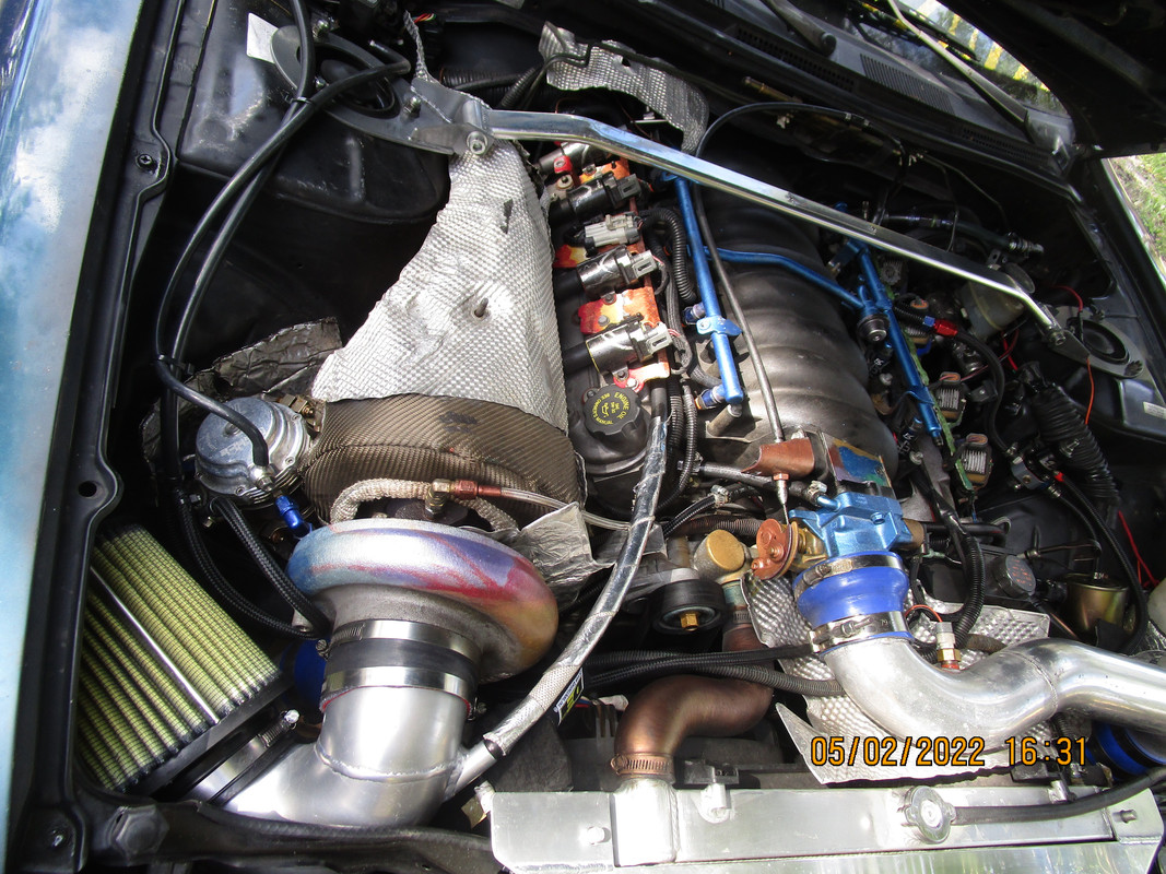
    People, This is what near perfection looks like, I've used exactly 1 LS engine and 1 4l80e transmission my entire life for myself.
    This stock bottom end engine approaching 240,000 miles with my 60,000 miles at 500-600rwhp for around 5 years, I consider a minimum output at 93 octane gasoline as a daily driver using a 'free' engine.


    Upgraded from Yank 2800 Single Disc to Yank 3200 Triple Disc.
    Behold ~18psi around 3,000rpm on a 2-bar OS , exceed and control well beyond g/cyl limit at 1.550g/cyl which they say is impossible but there it is perfection control perfect timing and a/f.
    Absolutely will need open loop to achieve these superior economy and cleaner spark plugs and reduced carbon deposits of lean air fuel ratios and control over the power enrichment thresholds to achieve mid-afr for mid-range torque.


    23-10-24 20-03-05.hpl
    23-10-25 14-18-58.hpl
    23-10-25 16-21-56.hpl
    23-10-25 19-45-14.hpl
    23-10-26 21-18-47.hpl
    23-10-26 23-02-21.hpl

    AEM WBO2.MathParameter.xml
    Channel.Channels.xml
    Charts.Charts.xml
    layout.Layout.xml


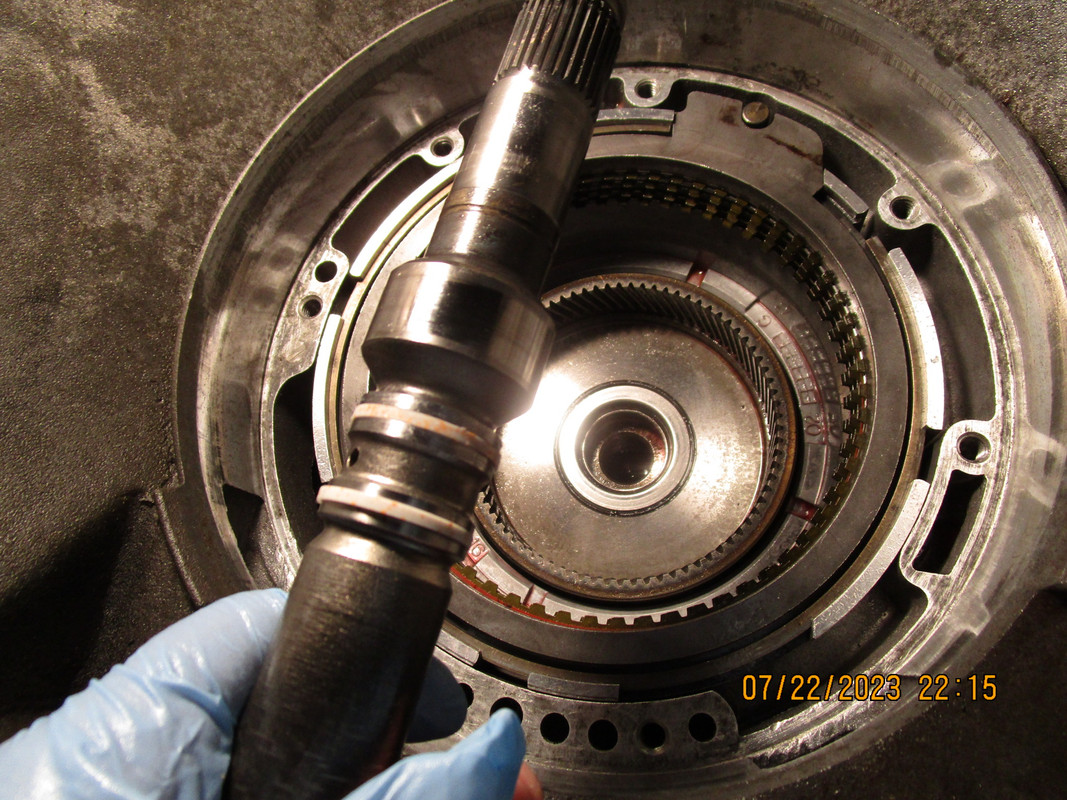
    I went through the transmission when I swapped the converter to check up on things.


    Never a catch can. This is absolutely paramount for engine longevity. My crankcase pressure at WOT with the new filter was around 1"Hg but with aging it shall approach 2" maybe even 3"Hg hopefully for additional crankcase scavenging which will further reduce blow-by and oil droplet suspension which will prevent oil leaks, protect oil seals, and keep oil inside the engine and out of the piston rings, and helps protect the turbocharger from particulate.


    LS engine do NOT have an oil problem. I will 600+rwhp on an LS Gen3/4 respectively 4.8/5.3/6.0 Stock engine for 200,000 miles with no catch can without issues.
    If you learn to control the crankcase pressure you will exert control on the oil system.


    I want to see Turbo cars doing this stuff perfectly on precious gen3 computers, It warms my heart