CORE Traction Control
Below outlines the recommended procedures to utilize both AI traction control and Conventional traction control.
Artificial Intelligence (AI) Traction Control
CORE's AI traction control maintains traction within a defined limit (Intelligent TC Slip Setpoint in mph) by reducing engine torque output through the following methods:
|
2.
|
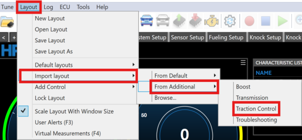
From the Menu Bar Click Layout > Import Layout >From Additional > Traction Control. |
|
3.
|
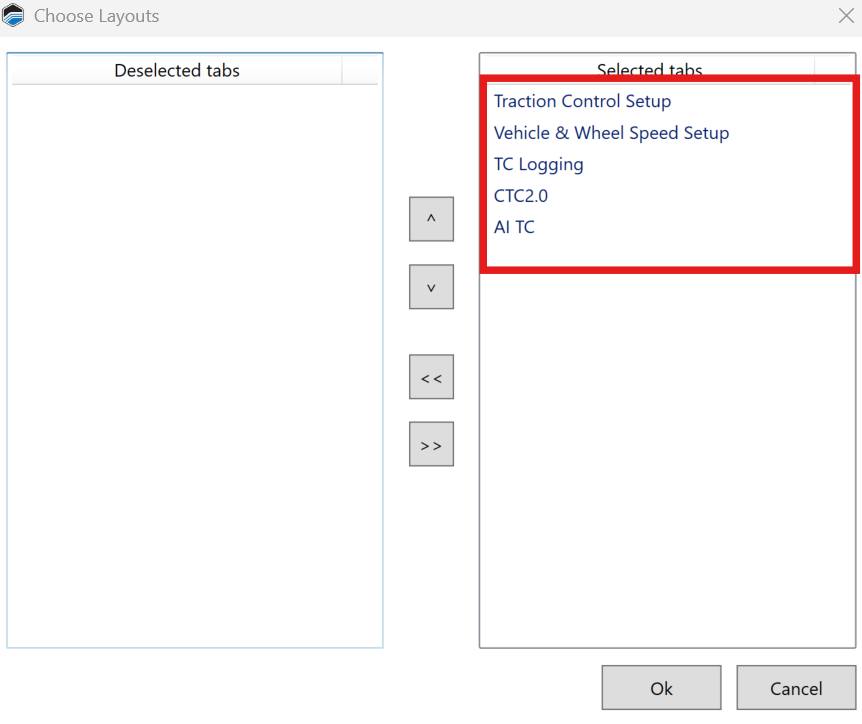
Ensure the below parameters are selected, then click Ok. |
|
4.
|
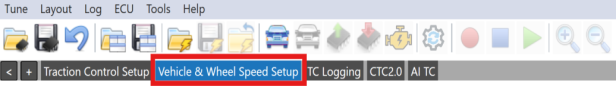
In the layout menu bar select the Vehicle & Wheel Speed Setup tab. |
|
5.
|
Ensure at least one Front & Rear Speed Sensor Fitted parameter is set to Yes. |
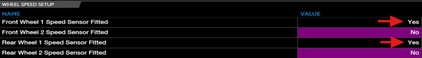
NOTE: Two Front & Rear Speed Sensor Fitted parameters can be set to Yes but only one for each need to be fitted to allow conventional traction control to work.
|
6.
|
Ensure both Front Wheel 1/2 (FL/FR Wheel Speed Sensor Input & Rear Wheel 1/2 (RL/RR Wheel Speed Sensor Input parameter is set to one of the eight correct corresponding channels. |
 Speed Sensor Input_616x86.png)
|
7.
|
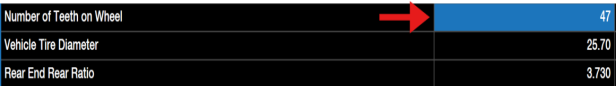
Ensure the Number of Teeth on Wheel is set to the correct value. |
|
8.
|
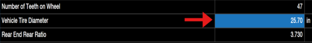
Ensure the Vehicle Tire Diameter is set to the correct value. |
|
9.
|
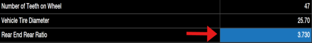
Ensure the Rear End Gear Ratio is set to the correct value. |
|
10.
|
Both Front Wheel Speed Selection Mode & Rear Wheel Speed Selection Mode need to be set to the following desired values: |
|
■
|
Average - Outputs average of front/rear wheel 1 (left) & rear wheel 2 (right) speeds. |
|
■
|
Minimum - Ouputs minimum of front/rear wheel 1 (left) & rear wheel 2 (right) speeds. |
|
■
|
Maximum - Outputs maximum of front/rear wheel 1 (left) & rear wheel 2 (right) speeds. |

|
11.
|
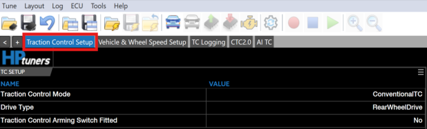
Click the Traction Control Setup layout tab. |
|
12.
|
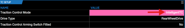
Ensure the Traction Control Mode parameter is set to IntelligentTC. |
|
13.
|
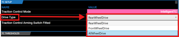
Select the corresponding Drive Type. |
|
14.
|
If you are utilizing any sort of switch to arm traction control, ensure to set the Traction Control Arming Switch Fitted parameter to Yes. |
|
15.
|
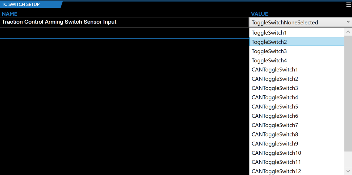
Ensure to set the Traction Control Arming Switch Sensor Input to the correct switch type value. |
|
16.
|
Set the Traction Control Vehicle Speed Threshold to the desired mph you want AI traction control to be enabled. |
|
17.
|
Set the Traction Control Vehicle Speed Threshold Hysteresis to the desired mph you want AI traction control to disable. |

|
18.
|
To adjust the desired wheel slip at different vehicle speeds, adjust the INTELLIGENT TRACTION CONTROL SLIP SETPOINT (MPH) table. |
_618x76.png)
|
19.
|
AI Traction control is now ready to be utilized. |
NOTE: If any issues occur while using AI traction control, utilize the below parameters to DEBUG any issues.
Conventional Traction Control
CORE's conventional traction control calculates wheel slip and utilizes a proportional integral (PI) controller to keep the vehicle slip under a defined limit (slip setpoint %) by reducing engine torque output through the following methods:
|
■
|
Ignition (spark) - Retard timing and/or completely cut individual cylinders. |
|
■
|
Injection (fuel) - Completely cut individual cylinders. |
|
■
|
Throttle Correction - Partially reduce the throttle position (partially close). |
|
■
|
Boost Wastegate Correction - Partially reduce the boost wastegate duty cycle or lower the boost setpoint. |
|
2.
|
From the Menu Bar Click Layout > Import Layout >From Additional > Traction Control. |
|
3.
|
Ensure the below parameters are selected, then click Ok. |
|
4.
|
In the layout menu bar select the Vehicle & Wheel Speed Setup tab. |
|
5.
|
Ensure at least one Front & Rear Speed Sensor Fitted parameter is set to Yes. |
NOTE: Two Front & Rear Speed Sensor Fitted parameters can be set to "Yes" but only one for each need to be fitted to allow conventional traction control to work.
|
6.
|
Ensure both Front Wheel 1/2 (FL/FR Wheel Speed Sensor Input & Rear Wheel 1/2 (RL/RR Wheel Speed Sensor Input parameter is set to one of the eight correct corresponding channels. |
|
7.
|
Ensure the Number of Teeth on Wheel is set to the correct value. |
|
8.
|
Ensure the Vehicle Tire Diameter is set to the correct value. |
|
9.
|
Ensure the Rear End Gear Ratio is set to the correct value. |
|
10.
|
Both Front Wheel Speed Selection Mode & Rear Wheel Speed Selection Mode need to be set to the following desired values: |
|
■
|
Average - Outputs average of front/rear wheel 1 (left) & rear wheel 2 (right) speeds. |
|
■
|
Minimum - Outputs minimum of front/rear wheel 1 (left) & rear wheel 2 (right) speeds. |
|
■
|
Maximum - Outputs maximum of front/rear wheel 1 (left) & rear wheel 2 (right) speeds. |
|
11.
|
Click the Traction Control Setup layout tab. |
|
12.
|
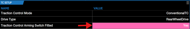
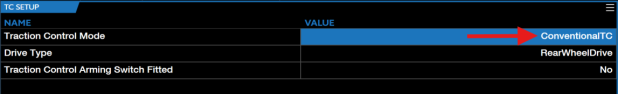
Ensure the Traction Control Mode parameter is set to ConventionalTC. |
|
13.
|
Select the corresponding Drive Type |
|
14.
|
If you are utilizing any sort of switch to arm traction control, ensure to set the Traction Control Arming Switch Fitted parameter to Yes. |
|
15.
|
Ensure to set the Traction Control Arming Switch Sensor Input to the correct switch type value. |
|
16.
|
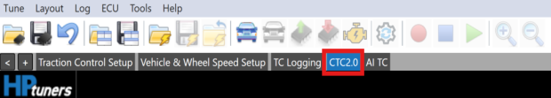
In the layout menu bar select the CTC2.0 tab. |
|
17.
|
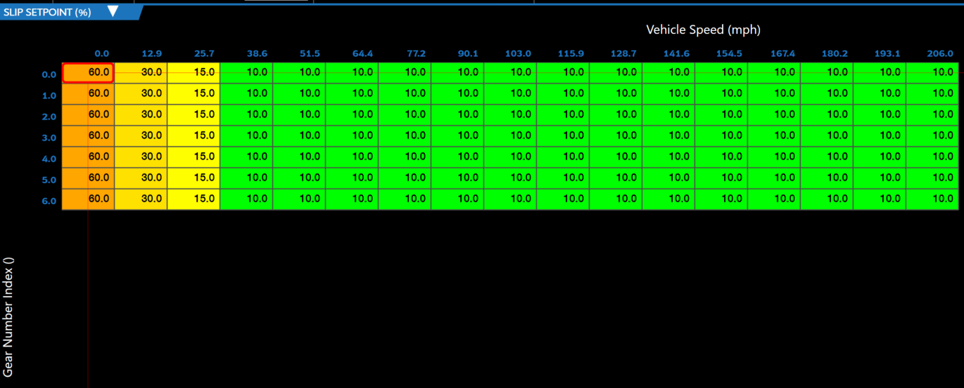
When tuning traction control, SLIP SETPOINT (%) is the table needed to tune traction control efficiently. |
|
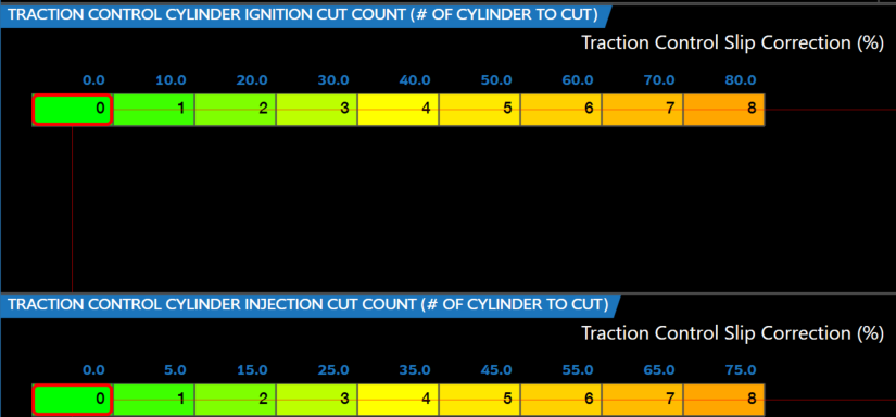
18.
|
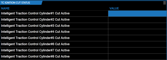
To adjust/correct the response of the controller (Slip Setpoint (%)) users need to change the values on both TRACTION CONTROL CYLINDER IGNITION CUT COUNT (# OF CYLINDER TO CUT) & TRACTION CONTROL CYLINDER INJECTION CUT COUNT (# OF CYLINDER TO CUT). |
NOTE: Conventional traction control can retard the spark timing on low over-sllip conditions and completely cut individual cylinder spark and high slip conditions. Tuners can adjust the phase 1 spark retard with the below table.
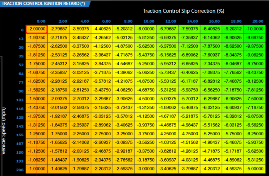
NOTE: The above table top axis represents low over-slip and cylinder ignition cut count table top axis represents high over-slip.
|
19.
|
Conventional traction control is now ready to be utilized. |

