
Sensors & Connectors
Below outlines each sensor and connector location, along with common sensor/connector part numbers supported with the CORE harnesses, as well as the Drive-By-Cable (DBC) and Drive-By-Wire (DBW) connector wire colors.
crankshaft position sensor
The crankshaft position sensor on most Gen III & IV LS engines can be found on the lower right-hand side of the engine block above the starter.
|
Generation |
OEM |
ACDelco |
|---|---|---|
|
Gen III |
12560228 |
213-354 |
|
Gen IV |
12585546 |
N?A |
Table 17. Crankshaft Supported Sensor Table
_200x310.png)
Figure 7. Crankshaft Position Sensor DBC & DBW Connector View
Camshaft Position Sensor
The camshaft position sensor on most Gen III LS engines can be found on the rear valley of the block behind the intake manifold.
The camshaft position sensor on most Gen IV LS engines can be found on the front of the engine on the front timing cover. Some may have an extension cable.
|
Generation |
OEM |
ACDelco |
|---|---|---|
|
Gen III |
12561211 |
213-363 |
|
Gen IV |
N/A |
213-3826 |
Table 18. Camshaft Supported Sensor Table

Figure 8. Camshaft Position Sensor DBC Connector View

Figure 9. Camshaft Position Sensor DBW Connector View
Throttle Position Sensor (TPS)
The throttle position sensor on most Gen III & IV LS engines can be found towards the front of the engine on the throttle/butterfly shaft assembly, which is only applicable to the Gen III Drive-By-Cable harness.
|
Generation |
OEM |
ACDelco |
|---|---|---|
|
Gen III |
17123852 |
213-912 |
|
Gen IV |
N/A |
N/A |
Table 19. TPS Supported Sensor Table
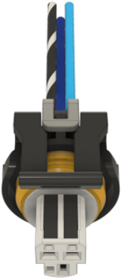
Figure 10. Throttle Position Sensor DBC Connector View
Accelerator Pedal Position Sensor
The accelerator pedal position sensor is located on the left side of the accelerator foot pedal, which is only applicable to the Gen IV Drive-By-Wire harness.
|
Generation |
OEM |
ACDeleco |
|---|---|---|
|
Gen III |
N/A |
N/A |
|
Gen IV |
Varies by Application |
Varies by Application |
Table 20. APP Supported Sensor Table
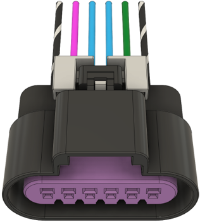
Figure 11. Accelerator Pedal Position Sensor DBW Connector View
Manifold Absolute Pressure (MAP) Sensor
The MAP sensor on most Gen III & Gen IV LS engines can be found on top of the intake manifold.
|
Generation |
OEM |
ACDelco |
|---|---|---|
|
Gen III |
19418810 |
12614970 |
|
Gen IV |
12591290 12644228 |
213-4434 |
Table 21. MAP Supported Sensor Table
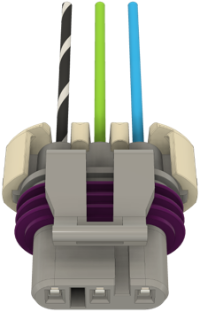
Figure 12. Manifold Absolute Pressure Sensor DBC Connector View
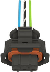
Figure 13. Manifold Absolute Pressure Sensor DBW Connector View
Engine Coolant Temperature (ECT) Sensor
The coolant temperature sensor on most Gen III & IV LS engines can be found on the driver side bank 1 cylinder head.
|
Generation |
OEM |
ACDeleco |
|---|---|---|
|
Gen III |
15326388 |
213-953 |
|
Gen IV |
15326388 |
213-953 |
Table 22. ECT Supported Sensor Table
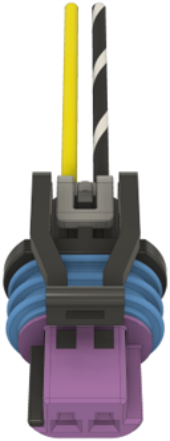
Figure 14. Engine Coolant Temperature Sensor DBC & DBW Connector View
Intake Air Temperature (IAT) Sensor
The IAT sensor on most Gen III LS engines is located on the intake pipe separate and not incorporated into the MAF sensor.
The IAT sensor on most Gen IV LS engines is located on the intake pipe that is usually incorporated into the MAF.
NOTE: Both the Terminated Gen III Drive-By-Cable & Gen IV Drive-By-Wire harnesses will have a 5 wire MAF that integrates with the IAT. Customers will have to purchase an adapter harness from EFI and/or BP to split the 2 wire IAT sensor.
|
Generation |
OEM |
ACDelco |
|---|---|---|
|
Gen III |
12160244 (N/A with 5 wire MAF) |
213-243 (N/A with 5 wire MAF) |
|
Gen IV |
12160244 |
213-243 |
Table 23. IAT Supported Sensor Table
Oil Pressure Sensor
The oil pressure sensor on most Gen III & IV LS engines can be found towards the back on the engine, above the flywheel housing.
|
Generation |
OEM |
|---|---|
|
Gen III |
12677836 |
|
Gen IV |
12673134 |
Table 24. Oil Pressure Supported Sensor Table
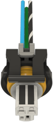
Figure 15. Oil Pressure Sensor DBC Connector View
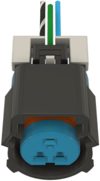
Figure 16. Oil Pressure Sensor DBW Connector View
Lambda Sensor (Oxygen Sensor)
Both upstream lambda sensors can be found after the exhaust manifold flanges and before the catalytic converter on each bank.
|
Generation |
BOSCH |
|---|---|
|
Gen III |
17025 |
|
Gen IV |
17025 |
Table 25. Lambda Supported Sensor Table
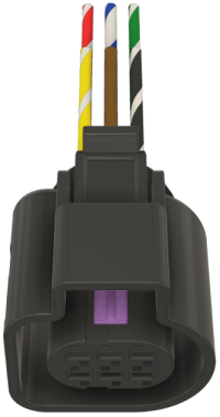
Figure 17. Lambda 1 Sensor DBC & DBW Connector View
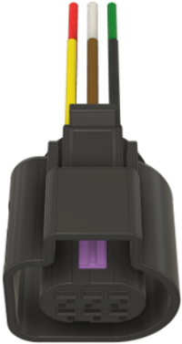
Figure 18. Lambda 2 Sensor DBC & DBW Connector View
Knock Sensor
Both knock sensors on most Gen III LS engines can be found under the valley and uses an extension harness with one connector.
Both knock sensors on most Gen IV LS engines can be found on the lower sides of the engine block in front of the starter motor or near the motor mounts and uses a separate connector for each knock sensor.
|
Generation |
OEM |
ACDelco |
|---|---|---|
|
Gen III |
12673134 |
213-3521 |
|
Gen IV |
N/A |
213-1576 |
Table 26. Knock Supported Sensor Table
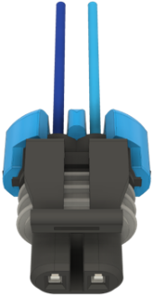
Figure 19. Knock Sensor DBC Connector View
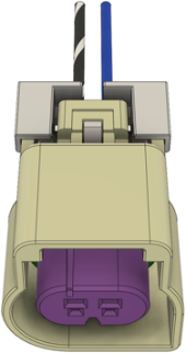
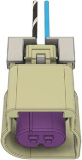
Figure 20. Knock Sensor 1 & 2 DBW Connector View
Mass Air Flow (MAF) Sensor
The MAF sensor on most Gen III & IV LS engines can be located on the intake tube.
NOTE: Both the Terminated Gen III Drive-By-Cable & Gen IV Drive-By-Wire harnesses will have a 5 wire MAF that integrates with the IAT. Customers will have to purchase an adapter harness from EFI to split the 3 wire MAF sensor.
|
Generation |
OEM |
ACDelco |
|---|---|---|
|
Gen III |
25179711 (3 wire MAF, IAT Required) |
213-364 (3 wire MAF, IAT Required) |
|
25168491 (5 wire MAF, applicable for LS1, LS2, & LS6) |
213-4657 (5 wire MAF, applicable for LS1, LS2, & LS6) |
|
|
Gen IV |
15865791 |
213-4222 |
Table 27. MAF Supported Sensor Table
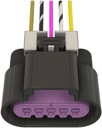
Figure 21. Mass Air Flow DBC & DBW Connector View
Fuel Injectors
The fuel injectors are located on top of the intake manifold on both the left and right banks.

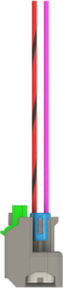
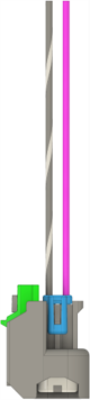
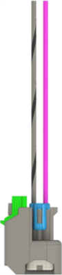
Figure 22. Fuel Injectors 1-4 DBC & DBW Connector View


Figure 23. Fuel Injectors 5-8 DBC & DBW Connector View
Ignition Coils
The ignition coils are located on both the left and right valve covers with a total of two connections, one for each bank.
|
Generation |
OEM |
ACDelco |
|---|---|---|
|
Gen III |
Varies by Application |
Varies by Application |
|
Gen IV |
Varies by Application |
Varies by Application |
Table 28. Ignition Coil Supported Table
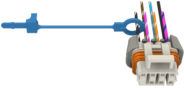
Figure 24. Ignition Coil Bank 1 DBC & DBW Connector View
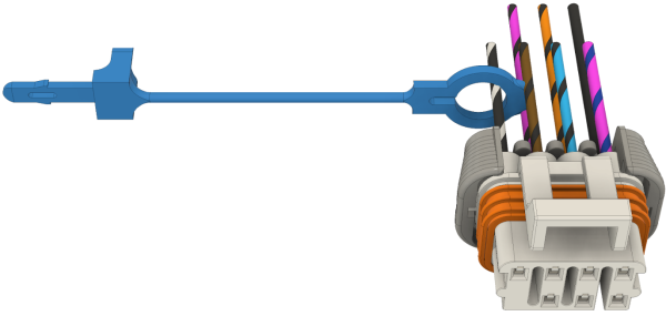
Figure 25. Ignition Coil Bank 2 DBC & DBW Connector View
NOTE: First dozen DBC & DBW harnesses will NOT have the blue trace on the 12v ignition wire, this does not affect the functionality of either harness.
Barometric Pressure Sensor
The barometric pressure sensor is often located on the fire wall on the right-hand side of the A/C blower motor when it’s a standalone sensor. When it’s not a standalone unit, the MAP and barometric pressure sensor are the same sensor.
|
Generation |
OEM |
|---|---|
|
Gen III |
30-2130-15 |
|
Gen IV |
30-2130-15 |
Table 29. Barometric Pressure Supported Sensor Table
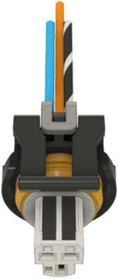
Figure 26. Barometric Pressure Sensor DBC & DBW Connector View
Vehicle Speed Sensor
The vehicle speed sensor is often on the driver near side of the transmission.
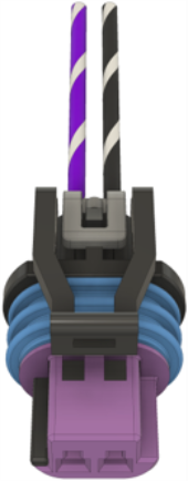
Figure 27. Vehicle Speed Sensor DBC & DBW Connector View
Alternator Connector
The alternator connector is located ont he back side of the alternator.
|
Generation |
OEM |
ACDelco |
|---|---|---|
|
Gen III |
Any 4 Cavity Connector |
Any 4 Cavity Connector |
|
Gen IV |
Any 4 Cavity Connector |
Any 4 Cavity Connector |
Table 30. Alternator Supported Connector Table
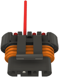
Figure 28. Alternator DBC & DBW Connector View
Throttle Body Connector
The throttle body connector is located on the throttle body itself. The below table specifies the recommended part numbers for the gen III harness, any throttle body can be used with the gen III harness, if the same style IAC and TPS sensor are used along with the throttle body.
|
Generation |
OEM |
|---|---|
|
Gen III |
TPS: 17123852 IAC: 17113598 |
|
Gen IV |
12570790 |
Table 31. Throttle Body Supported Connector Table
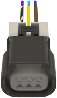
Figure 29. Throttle Body Connector DBW Connector View
Idle Air Control Valve
The idle air control valve is located directly above the right-hand side of the intake manifold or often on the throttle body.
|
Generation |
OEM |
ACDelco |
|---|---|---|
|
Gen III |
17113391 |
217-1806 |
|
Gen IV |
N/A |
N/A |
Table 32. Idle Air Control Supported Valve Table
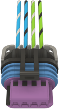
Figure 30. Idle Air Control Valve DBC Connector View
CAN Connectors
The CAN connectors are located by the fuse box, close to the ECU side of the harness.
|
Generation |
DT Connector |
|---|---|
|
Gen III |
AT04-4P TPA-AW4P Terminal - AT60-202-16141 |
|
Gen IV |
AT04-4P TPA-AW4P Terminal - AT60-202-16141 |
Table 33. CAN Supported Connector Table
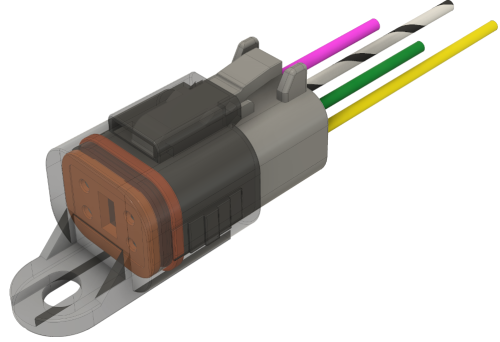
Figure 31. CAN BUS 1 (Deutsch) DBC & DBW Connector View
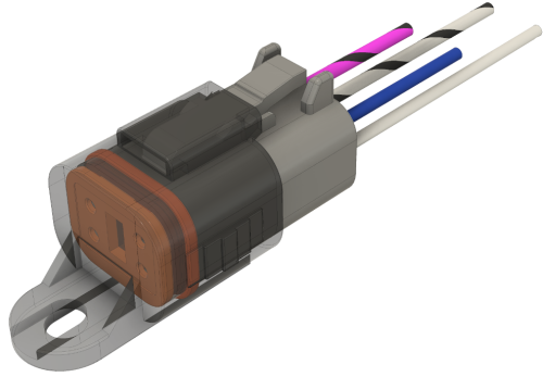
Figure 32. CAN BUS 2 (Deutsch) DBC & DBW Connector View
I/O Connector
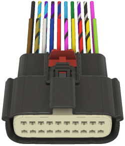
Figure 33. I/O (Molex) DBC & DBW Connector View
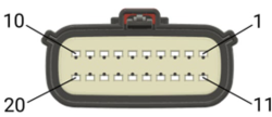
Figure 34. I/O (Molex) Pin 1-20 Connector View
