
Wiring Harness
This section outlines the available harnesses for CORE. Utilize the below electrical schematics for the four main CORE harnesses:
| ■ | Gen III LSX Drive-By-Cable Electrical Schematic |
| ■ | Gen IV LSX Drive-By-Wire Electrical Schematic |
| ■ | 4L60E & 4L80E Transmission Control Electrical Schematic |
| ■ | 5ft I/O Expansion Electrical Schematic |
Terminated Gen III Drive-By-Cable LSX CORE ECU Harness
On this harness the knock sensors are located in the valley. The MAP sensor and Cam sensor are located on the back of the engine. EV1 and EV6 connectors can be purchased with this harness to allow usage of the OEM connector style Gen III LS application.

Figure 36. Drive-By-Cable Harness Assembly
NOTE: The EV6 injector is standard on the Gen III Drive-By-Cable harness.
NOTE: The Gen III Drive-By-Cable harness is wired for 2 Bosch 4.9 LSU (Laser Sensor Unit) sensors.
NOTE: Can 1 and Can 2 come pre-terminated with DT (Deutsch) connector for easy use with aftermarket products.
NOTE: 20 pin I/O expansion connector is standard for the Gen III Drive-By-Cable harness. It can be paired with either additional I/O flying lead harness or 4L60e/4L80e expansion harness for direct plug in and play to the 4L60e and 4L80e transmission setups.
Terminated Gen IV Drive-By-Wire LSX CORE ECU Harness
This harness has an electronically controlled throttle body, along with an accelerating pedal feeding a signal to the ECU to control the electronic throttle. On the Gen IV Drive-By-Wire harness the MAP and Cam sensor are both located on the front of the engine. The knock sensors are located on the sides of the engine, which is different from the Gen III Drive-By-Cable harness.
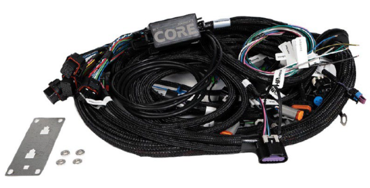
Figure 37. Drive-By-Wire Harness Assembly
NOTE: The EV6 injector is standard on the Gen IV Drive-By-Wire harness.
NOTE: The Gen IV Drive-By-Wire harness MAP sensors wiring is long enough to go to either front or rear of the intake manifold.
NOTE: The Gen IV Drive-By-Wire harness is wired for 2 Bosch 4.9 LSU (Laser Sensor Unit) sensors.
NOTE: Can 1 and Can 2 come pre-terminated with DT (Deutsch) connector for easy use with aftermarket products.
NOTE: 20 pin I/O expansion connector is standard for the Gen III Drive-By-Cable harness. It can be paired with either additional I/O flying lead harness or 4L60e/4L80e expansion harness for direct plug in and play to the 4L60e and 4L80e transmission setups.
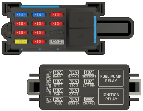
Figure 38. Fuse & Relay DBC & DBW Center Assembly
Unterminated 15’ Flying Lead CORE ECU Harness
This harness comes with the four ECU connectors along with the 15 ft sections of wiring already pinned for the ECU connector. This kit provides cavity plugs for the cavities not being used.
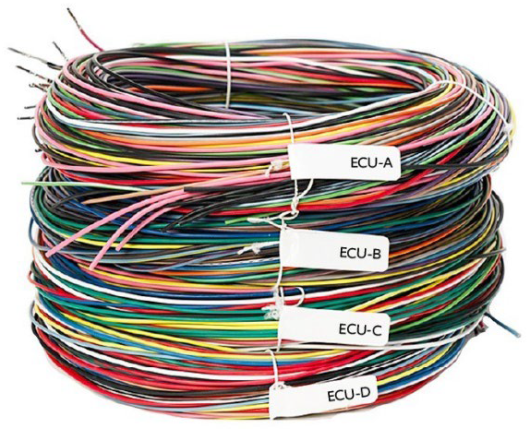
Figure 39. Flying Lead Harness Assembly
4L60E/4L80E Transmission Control CORE ECU Sub Harness
This is a single plug-in solution harness for the 4L60e & 4L80e transmission. Below outlines the 4L60e & 4L80e harness pinouts and I/O type.
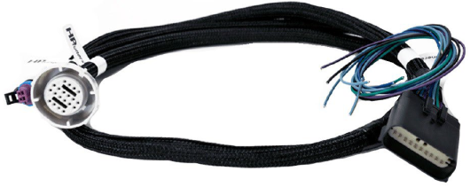
Figure 40. 4L60e & 4L80e Harness Assembly
|
Pin |
Color |
Comments |
|---|---|---|
|
1 |
LT GRN |
4L60E CAVITY A - 1-2 SHIFT SOLENOID VALVE CONTROL |
|
4L80E CAVITY A - 1-2 SHIFT SOLENOID VALVE CONTROL |
||
|
2 |
YEL/BLK |
4L60E CAVITY B - 2-3 SHIFT SOLENOID VALVE CONTROL |
|
4L80E CAVITY B - 2-3 SHIFT SOLENOID VALVE CONTROL |
||
|
3 |
RED/BLK |
4L60E CAVITY C - PRESSURE CONTROL SOLENOID VALVE HIGH CONTROL |
|
4L80E CAVITY C - PRESSURE CONTROL SOLENOID VALVE HIGH CONTROL |
||
|
4 |
YEL |
4L60E CAVITY L - TRANS FLUID TEMPERATURE SENSOR SIGNAL |
|
4L80E CAVITY L - TRANS FLUID TEMPERATURE SENSOR SIGNAL |
||
|
5 |
PNK/BLK |
4L60E CAVITY N - TRANS RANGE SWITCH SIGNAL A |
|
4L80E CAVITY N - TRANS RANGE SWITCH SIGNAL A |
||
|
6 |
RED |
4L60E CAVITY P - TRANS RANGE SWITCH SIGNAL C |
|
4L80E CAVITY P - TRANS RANGE SWITCH SIGNAL C |
||
|
7 |
DK BL |
4L60E CAVITY R - TRANS RANGE SWITCH SIGNAL B |
|
4L80E CAVITY R - TRANS RANGE SWITCH SIGNAL B |
||
|
8 |
WHT |
4L60E CAVITY S - 3-2 SHIFT SOLENOID VALVE CONTROL |
|
4L80E CAVITY S - TCC PWM SOLENOID VALVE CONTROL |
||
|
9 |
TAN/BLK |
4L60E CAVITY T - TCC SOLENOID VALVE CONTROL |
|
4L80E - NOT USED |
||
|
10 |
BRN |
4L60E CAVITY U - TCC PWM SOLENOID VALVE CONTROL |
|
4L80E - NOT USED |
||
|
11 |
PNK |
4L60E CAVITY E - 12V IGNITION |
|
4L80E CAVITY E - 12V IGNITION |
||
|
12 |
BLK/WHT |
4L60E CAVITY D - PRESSURE CONTROL SOLENOID VALVE LOW REFERENCE 4L60E CAVITY M - TRANS FLUID TEMP SENSOR LOW REFERENCE |
|
4L80E CAVITY D - PRESSURE CONTROL SOLENOID VALVE LOW REFERENCE 4L80E CAVITY M - TRANS FLUID TEMP SENSOR LOW REFERENCE ISS CAVITY B - INPUT SHAFT SPEED SENSOR LOW |
||
|
13 |
PPL/WHT |
4L80E - NOT USED |
|
ISS CAVITY A - INPUT SHAFT SPEED SENSOR SIGNAL |
||
|
14 |
DK GRN |
LOOSE - POSSIBLY TO BE USED FOR 0-5V LINE PRESSURE SENSOR |
|
15 |
LT BLU |
LOOSE - ECU 5V REFERENCE 2 |
|
16 |
DK BLU/RED |
LOOSE - SPEED INPUT 3 |
|
17 |
PPL/BLK |
LOOSE - SPEED INPUT 4 |
|
18 |
LT BLU/PPL |
LOOSE - FREQUENCY/DIGITAL INPUT 2 |
|
19 |
LT BLU/YEL |
LOOSE - FREQUENCY/DIGITAL INPUT 3 |
|
20 |
BLK |
LOOSE - BATTERY NEGATIVE |
Table 36. 4L60e & 4L80e Harness I/O Pinout Description
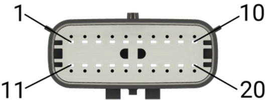
Figure 41. 4L60e & 4L80e Pin 1-20 Connector View
5ft CORE ECU I/O Sub Harness
This sub harness allows users the ability to utilize additional I/O when not utilizing the 4L60e/4L80e sub harness.
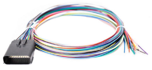
Figure 42. 5ft I/O Harness Assembly
|
Pin |
Color |
Comments |
|---|---|---|
|
1 |
LT GRN |
ECU A2 - 2A Low Side Driver Output 1 |
|
2 |
YEL/BLK |
ECU A8 - 2A Low Side Driver Output 2 |
|
3 |
RED/BLK |
ECU C5 - 5A High Side Driver Output 2 |
|
4 |
YEL |
ECU C34 - NTC Temperature Input 5 |
|
5 |
PNK/BLK |
ECU C30 - General Purpose Analog Input 9 |
|
6 |
RED |
ECU C32 - General Purpose Analog Input 11 |
|
7 |
DK BL |
ECU 31 - General Purpose Analog Input 10 |
|
8 |
WHT |
ECU A29 - 2A Low Side Driver Output 7 |
|
9 |
TAN/BLK |
ECU B22 - 2A Low Side Driver Output 4 |
|
10 |
BRN |
ECU B23 - 2A Low Side Driver Output 3 |
|
11 |
PNK |
12V Switched Ignition (10A Fused - "SENSORS" fuse in the fuse box) |
|
12 |
BLK/WHT |
ECU D2 - Sensor Ground |
|
13 |
PPL/WHT |
ECU A24 - Speed Input 2 |
|
14 |
DK GRN |
ECU C33 - General Purpose Analog Input 12 |
|
15 |
LT BLU |
ECU D5 - Sensor 5V Supply 2 |
|
16 |
DK BLU/RED |
ECU B9 - Speed Input 3 |
|
17 |
PPL/BLK |
ECU B21 - Speed Input 4 |
|
18 |
LT BLU/PPL |
ECU B16 - Frequency/Digital Input 2 |
|
19 |
LT BLU/YEL |
ECU B17 - Frequency/Digital Input 3 |
|
20 |
BLK |
Battery Negative |
Table 37. 5ft Sub-Harness I/O Pinout Description
Figure 43. 5ft I/O Pin 1-20 Connector View
