Page 1 of 2 12 LastLast
Results 1 to 20 of 34

Thread: GMTECH'S Latest Cam Tables...

  1. #1
    Advanced Tuner
    Join Date
    Jan 2009
    Posts
    792

    GMTECH'S Latest Cam Tables...

    Since you guys had SO much fun with the Optimum Spark tables, I thought I'd throw these out there too!

    It's been a LONG time since I've posted my cam tables, mostly because they just ended up in the so called "professional" tuners tunes. I got tired of seeing my EXACT tables copied into tunes that guys were selling as their own. And not a word of feedback to help us all learn more either, just quietly stealing somebody else's work and making a profit on it because you're too stupid to figure it out yourself. (Not meant for anyone on here, or at least anyone that actually posts on here. Rant over!)

    So I figured screw it, there's some good guys on here and they deserve the info. So here they are. I think these are WAY different than the ones I posted on here like 2 years ago. These will probably be different than what I'll be running in 2 weeks anyway! I'm still learning on this stuff everyday, NOBODY knows it all.

    Here's the warnings...
    Please don't just paste these into your tunes without knowing a little bit of what you're doing. These tables work in MY car, my car is not like most others out there. I have a bigger (2.4L) throttle body for one thing, along with many other mechanical engine changes. One thing to notice, where my freeway cruise EGR section is. If you're tuning a Cobalt for instance, your freeway cruise rpm and load will be very different than mine. I have taller tires in back even, that will effect which cells you want to run what numbers in also.

    One thing I've finally got a handle on is not losing mpg and still retaining good throttle response and acceleration through all rpm's and loads. The latest tunes I've had are getting the best freeway mpg I've ever had. The biggest difference is the mpg isn't dropping off above 65-70mph like it used to. I'm getting almost 30mpg at 75-80mph flat ground cruising now! I think the biggest factor is intake timing. I did a TON of pulls with all kinds of cam timing over the last 2 or 3 years, and learned that the LNF likes intake advance.

    Here's what you can do to see if these tables work for you, or give you anything. Try ALL KINDS of pulls, especially down low in the rpm's. Like do a pull from 40 to 60 in 4th gear, you'll be starting out at like 2k rpm and it isn't gonna pull too hard, but it's a good test. Then try changing the cam tables, sometimes drastically is best, and do the same pull on the same stretch of road. I found adding in a bunch of intake advance consistently improved my times on pulls like that. Also a 3rd gear pull from 35mph or so, all the way to your rev limit. BTW, as you can see like most everyone else, I never got much better than stock cam timing at high rpm and high load areas. The stock settings, or a few degrees one way or another seem to work fine. Just depends on how much combustion chamber pressures you think your engine can take, and how fast you want the top end to rev out. Too much exhaust advance and it won't want to rev, too little and you'll be losing compression. Again, experiment with bigger numbers than you'd think so you can really see what's happening with your changes. Move one cell up or down one number and you're never gonna tell what it's doing. Try 10 or even 20 and see what it does.

    Have fun guys! Sorry for the head banging and frustration that might follow, as my Optimum Spark table thread seemed to do. I think a couple guys did figure it out and did get their cars running better though, didn't they?

    John

    Oh, btw, I have all other cam tables set to these same values. Meaning make cold, cat warmup, knock, idle, etc all the same. And also btw, these tables are NOT the absolute gospel best cam tables in existence, they work pretty good in my situation though. I'll always be tweaking them though!


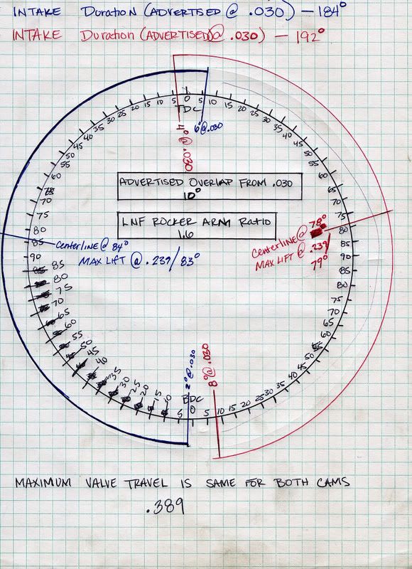
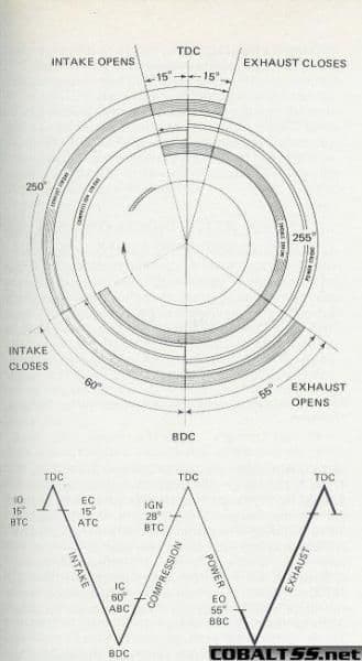
    I'm going to add some pictures that I've posted before but it's been awhile. These help explain the basics of cam timing.


    SB08 I stole this one from you didn't I?---


    Last edited by gmtech16450yz; 08-08-2012 at 11:27 AM. Reason: Added a bunch of cam timing info pictures

  2. #2
    Advanced Tuner projectlnf's Avatar
    Join Date
    Jun 2012
    Location
    warrenton va
    Posts
    465
    i have been fooling with the cam tables for a while now but i honestly only move them maybe a couple numbers at a time i never go to dramatic with them. but im going to try these and see if i can get more out of it i have noticed my power curve goes up slowly..
    2003 Ford excursion 6.0 PSD
    No limit intake
    Straight pipe
    Studded
    EGR delete
    KC billet single plane compressor wheel
    Self Tuned
    XDP Regulated return
    RDP Fuel sump
    AEM progressive water meth
    Custom suspension air bags
    8" lift
    35" tires

  3. #3
    Ill post mine up too, why not! I mainly messed with mine in terms of drivability... if it drives smooth and sounds a little more stout it must be a little better lol. I was running some real old tables a while back and noticed that the car would fall on its face after a shift just normal driving and then i noticed that around 1500-1750rpm there are three cells for 250rpm difference and the cams were moving too much! I smoothed them out and never looked back!

    Ill have to try out the increased intake advance down low and see how it feels! But right now with all thats done i average 28-29.5mpg driving to work in split driving and whenever i drive to the ocean on flat highways i average 31.5-32mpg in my cobalt... the readout on my dash is currently 30.0mpg haha

  4. #4
    Advanced Tuner projectlnf's Avatar
    Join Date
    Jun 2012
    Location
    warrenton va
    Posts
    465
    well i put them on.. it def picks up ALOT better than my old cam tables only problem i had was i was seeing alot more knock now.. before i had knock for the first few minutes of driving and it went away. now its only if i go above my load axis on my editor ex: in the editor my max load axis is 215 and my scanner says load is 237 then i knock real bad and my timing drops dramatically. as soon as the load comes down at the top of the rpm it clears right up almost instantly. and i can pull 18* up top? weird?


    im actually scaling my load axis in my editor to match my scanner to see if that helps and if im wrong please let me know lol
    2003 Ford excursion 6.0 PSD
    No limit intake
    Straight pipe
    Studded
    EGR delete
    KC billet single plane compressor wheel
    Self Tuned
    XDP Regulated return
    RDP Fuel sump
    AEM progressive water meth
    Custom suspension air bags
    8" lift
    35" tires

  5. #5
    Advanced Tuner silverbullet08's Avatar
    Join Date
    Dec 2009
    Location
    Houston, TX
    Posts
    453
    lol yea I can see simular tables popping up everywhere now. Thanks for sharing. I get mpg drop off after about 75mph, mine seemes to fall off from about 31-32 to about 28-29ish at around 85mph and steadly decrease. As far as the WOT area after I did my big turbo set up I started playing with the intake cam as well. I didnt advance in the lower rpm areas as much as you did because I seemed to pick up some kr in daily driving but from 3500 up we are within a degree or so haha. Guess thats a second on the factory cam settings being fairly decent up top. But just like you did I pulled my cruize area over and blended it with WOT. I Guess thats why my milage didnt seem to fall off too bad. Its also funny how a bigger turbo will net you better mpg for daily driving. Il give the lower rpm areas a shot again and see what it makes of it. What turbo did you end up going with btw?
    Last edited by silverbullet08; 08-08-2012 at 01:37 AM.
    HP-Unlimited Tuning and Custom Fabrication
    Houston area performance parts dealer
    MD800 Mustang Dyno 713-560-3889 Taylor
    2016 Camaro A8 "shop car" FIRST 6th GEN CAMARO OVER 200mph IN THE MILE 203.5mph

  6. #6
    Advanced Tuner
    Join Date
    Jan 2009
    Posts
    792
    Added some pics to the first post. Hopefully they help and don't cause more confusion! Damn learning hurts my brain sometimes! I can stare at graphs and diagrams for hours and theorize them to death, but sometimes I just have to go out and try stuff to see what it actually does. Theory doesn't always play out perfectly in the real world.

    SB08- I've got an EFR 6758 with a pretty efficient tube manifold feeding it.

    Yeah, WOT cam timing change gains have been pretty much exhausted by many of us, stock settings are about it except for minor rev out changes like I've mentioned. Acceleration and low rpm pull out changes can be huge though. Drivability and throttle response changes can also be huge.

    What you guys are seeing with the KR is what I mentioned about cylinder pressures. You're changing dynamic compression with these cam timing changes. I'm running E47 and I don't have stock pistons so I'm not as concerned about going too high on dynamic compression, down low or up high in the rpm's. If you're on pump gas or stock pistons, you'll most definitely want to do different things with cam timing. Same with stock turbo (or stock turbine housing), you aren't going to want a whole bunch of dynamic compression at high rpm's with the stock turbo, that's asking for trouble.

    Keep up the good work guys! Aint lurnin fun? I had lunch with my Engineer buddy yesterday and we were talking about how amazing it is that changing a couple numbers in some software will either make or lose huge amounts of power in an engine. That right there is what keeps me staring at those lines and numbers in my logs and tunes! It's like modern day mining, "There's Horse Power to be found in them thar 0's and 1's, we just need to find them!"

  7. #7
    Advanced Tuner silverbullet08's Avatar
    Join Date
    Dec 2009
    Location
    Houston, TX
    Posts
    453
    Quote Originally Posted by gmtech16450yz View Post
    SB08- I've got an EFR 6758 with a pretty efficient tube manifold feeding it.

    Yeah, WOT cam timing change gains have been pretty much exhausted by many of us, stock settings are about it except for minor rev out changes like I've mentioned. Acceleration and low rpm pull out changes can be huge though. Drivability and throttle response changes can also be huge.

    Keep up the good work guys! Aint lurnin fun? I had lunch with my Engineer buddy yesterday and we were talking about how amazing it is that changing a couple numbers in some software will either make or lose huge amounts of power in an engine. That right there is what keeps me staring at those lines and numbers in my logs and tunes! It's like modern day mining, "There's Horse Power to be found in them thar 0's and 1's, we just need to find them!"
    Im running a fairly good flowing manifold as well. 1.5" runners equal length. I believe that diagram above came from cobaltoverbooster. After looking at those injection timing modes I came up with a few theories. I may go test them later today.

    Hey Cobaltoverbooster. I remember a while back you posted up a excel spreadsheet that would give overlap based on what changes you made in the intake and exhaust. I looked around for it for a while but couldnt find it. This would be a good place to put it if you would.
    HP-Unlimited Tuning and Custom Fabrication
    Houston area performance parts dealer
    MD800 Mustang Dyno 713-560-3889 Taylor
    2016 Camaro A8 "shop car" FIRST 6th GEN CAMARO OVER 200mph IN THE MILE 203.5mph

  8. #8
    Senior Tuner cobaltssoverbooster's Avatar
    Join Date
    Dec 2008
    Location
    Nevada
    Posts
    4,452
    It didn't work out lol but remeber this....0 and 0 equal the point where overlap and no overlap meet. The more negative the intake and more positive the exhaust the more overlap u have. Each value of change is 1 degree.
    2000 Ford Mustang - Top Sportsman

  9. #9
    Advanced Tuner
    Join Date
    Jan 2009
    Posts
    792
    Quote Originally Posted by cobaltssoverbooster View Post
    It didn't work out lol but remeber this....0 and 0 equal the point where overlap and no overlap meet. The more negative the intake and more positive the exhaust the more overlap u have. Each value of change is 1 degree.
    Yeah since these cam phasers can only advance the intake cam and retard the exhaust cam, pretty much any movement you do to them is going to increase overlap.

  10. #10
    Senior Tuner cobaltssoverbooster's Avatar
    Join Date
    Dec 2008
    Location
    Nevada
    Posts
    4,452
    I can work on the excel file but it's not gonna have 0.050" values
    Last edited by cobaltssoverbooster; 08-12-2012 at 11:53 AM.
    2000 Ford Mustang - Top Sportsman

  11. #11
    Senior Tuner cobaltssoverbooster's Avatar
    Join Date
    Dec 2008
    Location
    Nevada
    Posts
    4,452
    In the very first post, the drawn graph at the bottom is a graph that i made by degreeing the camshafts when the vehicle was off for over 5 hours. my hopes were to see the phasers in their rest positions but problem is at rest the phaser go two different ways and since they dont have sprongs in them forcing them to their on vehicle forced rest positions these tables are innacurate. (when the vehicle is on the phaser have oil control seating them. i overlooked this part when degreeing the cams.) with that, the only things accurate on the graph i drew are duration and valve rocker ratios.


    Now for the overlap chart its attached. there are things to keep in mind.
    The first tab is where you place the cam table values you are running in your tune. The second table shows u the overlap based on an 0.00" valve opening duration spec. if you want to see over lap at an 0.050" you make a value of 16 the new 0 overlap value.

    exapmle time:
    Intake cam chart says -1 = 1* of overlap. at 0.050" -17 equals overlap by 1*.
    Exhaust cam chart says 1 = 1* of overlap. at 0.050" 17 equals overlap by 1*.

    *NOTE: you will have to calculate the 0.050" values on your own.


    Also, people always get confused on which way the cams are moving. lets set that straight once and for all. As you can see in the first post/last picture we have a generic domestic cam card. although it is overlap wise innacurate it will serve my purpose.(JDM/Metric cards tend to lay theirs out in linear form showing exhaust on the left and intake on the right)

    When reading a domestic cam card you read it in a counter clockwise direction. Notice the red(exhaust) valve is on the right side? it gets read as the first event, so it opens then overlap, it closes. for blue(intake) on the left side it opens for overlap and then closes for compression. so, by reading this chart correctly you can see that the cam phasers are advancing the opening of the intake valve into the exhaust cycle for more overlap. the opposite is now true for the exhaust, it gets the valve opening retarded into the intake cycle for more overlap. Thus, positive values retard, and negative values advance.
    Last edited by cobaltssoverbooster; 08-12-2012 at 12:04 PM.
    2000 Ford Mustang - Top Sportsman

  12. #12
    Advanced Tuner
    Join Date
    Jan 2009
    Posts
    792
    I honestly think that we're not smart enough to theorize this stuff, trial and error seems to be the best approach.

    The reason I say this is because we're dealing with TWO adjustable cams, Direct Injection and a Turbo. I know some stuff, but I'm not sure I can honestly handle some of the theories behind this many variables. Add in the fact that you make a change in cam timing and in this wonderful Bosch computer it effects your throttle angles (and probably 50 other things!), this is about as difficult as it gets to do objective testing.

    That's why I depend so much on logging and elapsed times over speed runs. Doing the exact same run on the exact same stretch of road over and over gives you some pretty darn consistent results. Doing things like 35 to 100+ runs gives you a pretty good idea of power changes at EVERY area of the rpm range. I know none of this is dyno tuning, but there's things I REALLY don't like about dyno tuning anyway. I just got a log from a guy that did a couple dyno runs yesterday. The conditions were SO different than street runs the tune was completely off. IAT temps were abnormally high, and the dyno operator did the run so quickly after starting the engine 3/4's of the run were in open loop.

    So don't waste a bunch of time doing Excel stuff, I'm not sure how much help it will actually give us. I've been logging overlap for awhile, and guess what? Theory doesn't match real world results on these motors. Here's what you guys can do if you want to gain some power and knowledge...

    Try plugging in some big number changes in certain specific areas of the cam tables. Do a couple runs and compare the times and logs to your baseline. Then go the other direction with the same number changes in the same certain areas, run and log, repeat, repeat, repeat........... Make the changes at LEAST 10 degrees, otherwise you're never gonna see any changes. For instance, if you've got +25 in a certain cell in your stock tune, try +15, then +35. You should be able to see changes with those kinds of numbers. If you gain in one and loose in another, narrow your changes and concentrate on the direction that gained. If you loose in both, again, narrow your changes until you get back to where you started. (There might not be any gains, only losses.)

    Good luck!

  13. #13
    Senior Tuner cobaltssoverbooster's Avatar
    Join Date
    Dec 2008
    Location
    Nevada
    Posts
    4,452
    they wanted it i gave it to them.
    i already know it doesnt help anything. only thing it was good for was overlap idle control and gettign a loped idle.
    2000 Ford Mustang - Top Sportsman

  14. #14
    Advanced Tuner
    Join Date
    Jan 2009
    Posts
    792
    Quote Originally Posted by cobaltssoverbooster View Post
    In the very first post, the drawn graph at the bottom is a graph that i made by degreeing the camshafts when the vehicle was off for over 5 hours. my hopes were to see the phasers in their rest positions but problem is at rest the phaser go two different ways and since they dont have sprongs in them forcing them to their on vehicle forced rest positions these tables are innacurate. (when the vehicle is on the phaser have oil control seating them. i overlooked this part when degreeing the cams.) with that, the only things accurate on the graph i drew are duration and valve rocker ratios.


    Now for the overlap chart its attached. there are things to keep in mind.
    The first tab is where you place the cam table values you are running in your tune. The second table shows u the overlap based on an 0.00" valve opening duration spec. if you want to see over lap at an 0.050" you make a value of 16 the new 0 overlap value.

    exapmle time:
    Intake cam chart says -1 = 1* of overlap. at 0.050" -17 equals overlap by 1*.
    Exhaust cam chart says 1 = 1* of overlap. at 0.050" 17 equals overlap by 1*.

    *NOTE: you will have to calculate the 0.050" values on your own.


    Also, people always get confused on which way the cams are moving. lets set that straight once and for all. As you can see in the first post/last picture we have a generic domestic cam card. although it is overlap wise innacurate it will serve my purpose.(JDM/Metric cards tend to lay theirs out in linear form showing exhaust on the left and intake on the right)

    When reading a domestic cam card you read it in a counter clockwise direction. Notice the red(exhaust) valve is on the right side? it gets read as the first event, so it opens then overlap, it closes. for blue(intake) on the left side it opens for overlap and then closes for compression. so, by reading this chart correctly you can see that the cam phasers are advancing the opening of the intake valve into the exhaust cycle for more overlap. the opposite is now true for the exhaust, it gets the valve opening retarded into the intake cycle for more overlap. Thus, positive values retard, and negative values advance.

    That's the big one that we all had trouble with at first. When I first started looking at the LNF tables, I remember looking at the cam tables and scratching my head! The GM Service Information description and operation, was the first thing I looked at. When it said the cam phasers ONLY ADVANCE THE INTAKE AND ONLY RETARD THE EXHAUST it all made more sense. Those points, and what you said that I put in bold NEED to be understood for anyone to make sense of tuning these engines. Thanks!

  15. #15
    Senior Tuner cobaltssoverbooster's Avatar
    Join Date
    Dec 2008
    Location
    Nevada
    Posts
    4,452
    idk about you but i get pm's constantly for that. it was time it got mentioned in a proper cam thread again.
    2000 Ford Mustang - Top Sportsman

  16. #16
    Advanced Tuner |V3nom|'s Avatar
    Join Date
    Apr 2009
    Location
    Denham Springs, LA
    Posts
    418
    i havent made any cam changes so whats the best thing to do first? i think i saw somewhere about making all the intake and exhaust tables the same as the warm tables but i want to be sure before i start making changes.
    2008 Sky RL

  17. #17
    Senior Tuner cobaltssoverbooster's Avatar
    Join Date
    Dec 2008
    Location
    Nevada
    Posts
    4,452
    Making them the same just limits the differences and makes it command a desired value better. I say better cause we all know it still does what it wants.
    2000 Ford Mustang - Top Sportsman

  18. #18
    Advanced Tuner |V3nom|'s Avatar
    Join Date
    Apr 2009
    Location
    Denham Springs, LA
    Posts
    418
    haha yeah i hear ya.

    so to start all i do is take the main (warm) table and post it over the main (cold) table for both the intake and exhaust base angle tables?

    are there any other tables that need to be changed before making adjustments to the cam tables themselves?
    2008 Sky RL

  19. #19
    Tuner in Training
    Join Date
    Aug 2010
    Posts
    12
    What you do is make the Main(Warm)[Base Angle], Main(Cold)[Base Angle], Knock[Knock Angle], Main(Warm)[Catalyst Heating], Main(Cold)[Catalyst Heating] all equal to one another. The Intake and Exhaust side will have different tables so don't make them all identical for both.

    Be sure to do the same for the Idle tables as well.

  20. #20
    Senior Tuner cobaltssoverbooster's Avatar
    Join Date
    Dec 2008
    Location
    Nevada
    Posts
    4,452
    since this is a cam thread, does anyone know what the scanner pid is to see what kind of signal the phaser solenoids are recieving? trying to find out exactly what kind of signal they recieve.....right know im betting highly on DC% control signals.
    2000 Ford Mustang - Top Sportsman