Results 1 to 4 of 4

Thread: NO BS way to wire up and setup HPTuners for LC1

  1. #1
    Tuner
    Join Date
    Nov 2008
    Location
    Hampton, VA
    Posts
    75

    NO BS way to wire up and setup HPTuners for LC1

    Is there a no bullshit way to setup HPtuners pro for the Innovate LC-1 wideband sensor?

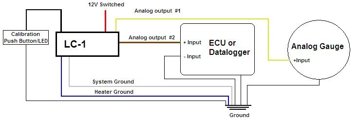
    I have done a search and read just about all the threads concerning the LC-1 but not one truly answers the right way to set everything up for the LC-1 to work with HPtuners pro. Can anyone help me out? I am aware that you take the LC-1 analog output #2 wire and connect it to the EIAO input 1 or 2 or 3 or 4 in HPtuners but beyond that I am not sure what forumula you use in HPtuners software for the offsets to make sure its accurate. Any help is appreciated.

  2. #2
    Senior Tuner
    Join Date
    Apr 2005
    Location
    Sugar Land, TX
    Posts
    1,198

  3. #3
    Advanced Tuner blownbluez06's Avatar
    Join Date
    Jan 2008
    Location
    Forney, TX
    Posts
    982
    don't forget to ground pin5 with a ground that is common with the LC-1 and the chassis.
    I like to use the factory default range of 7.35-22.39 for that you would use volts/.3324 + 7.35

    I have always used a gauge display to compare to my HPT values on my screen and used the VCM controller to command richer and leaner fuel to push it around so I know it's not only accurate around 14.7, but 10 and 16 as well. If not, I will change the slope or intercept as needed.
    Hsquared racing engines RHS 427, Procharger F2, Moran Billet Atomizer injectors, Alky Control,Mast LS7 heads, Nitrous outlet kit,Tilton quad disc clutch, DSS shaft, RKT56 ZR1 trans, RPM Quaife diff. Built and tuned by yours truly.

  4. #4
    Tuner in Training 1slowhoe's Avatar
    Join Date
    May 2011
    Location
    Little Rock, AR
    Posts
    16
    Quote Originally Posted by blownbluez06 View Post
    don't forget to ground pin5 with a ground that is common with the LC-1 and the chassis.
    I like to use the factory default range of 7.35-22.39 for that you would use volts/.3324 + 7.35

    I have always used a gauge display to compare to my HPT values on my screen and used the VCM controller to command richer and leaner fuel to push it around so I know it's not only accurate around 14.7, but 10 and 16 as well. If not, I will change the slope or intercept as needed.
    I assume that if you have the 7-wire LC-1 and you have the Green Analog ground wire, then you only need ONE wire going into the HPT EIO input? Is that correct? Or do I need ANOTHER ground wire to the #5 ground position on the EIO? If so, do I ground that wire to the same lug as the Heater, system, and Green Analog ground wire grounds? (I did not use the calibration wire as I am running a XD-16 guage.)I have mine wired per the instructions and this diagram sans the ground at the "ECU DATA LOGGER" I thought the green analog ground wire (grounded to the same lug as all the other grounds) eliminated the need for the "ECU DATA LOGGER" ground wire.
    I hope I'm wrong and that's why my XD-16 reads perfect and my HPT reads WAY off.

    All Innovate MTS devices like the LC-1 with dual serial ports should have their system grounds connected together to a common ground point. If an external data logger or ECU is to be fed by an MTS device, the MTS ground should be located at or near the ECU or data logger’s input signal ground. Some ECU’s or data loggers have differential inputs. A differential input has a
    separate ground INPUT for each sensor input. This ground input MUST be connected also to ground as shown in these diagrams. If one analog output of the LC-1 is used to drive an AFR display and the other output is used to connect to an ECU, the AFR display ground should be connected to the ECU ground. The schematics below can also be adapted for 7-wire LC-1s. Simply wire the Green analog ground wire with the System ground.