-
Tuner

2.25 Scanner, custom PIDs and MAF transfer for Coyote. Please help me fill the gaps
Ive spent hours searching both here and google and still haven't found the answers so hoping someone can assist.
I want to be ready when we will be able to get the Coyote Control Pack licensed which should be any day now. Ive read several threads about creating custom configs, pids and histrograms for creating and logging MAF transfer to determine % of error I need to correct with my custom MAF. When looking at 2.5, much of this is missing.
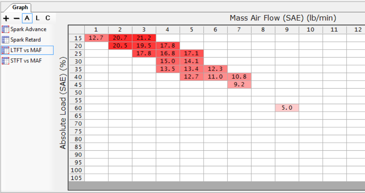
The MAF is the same diameter and very close to the same distance from the TB as the factory setup. With that said, Im getting 20+% LTFT in the lower flow areas, such as right off idle or light cruise. The car actually seems to miss / run rough taking off from idle, so I know there is a work to be done there.
My need is quite simple, but for the life of me, I must be missing something so hoping for some help.
With the current 2.5 build, how do i create a custom PID, or table, or Histo that will allow me to log my STFT and/or LTFT on a Coyote so that I can apply the % correction to the MAF curve and get the car closer to where it needs to be?
I dont see where you can create custom PIDs in 2.5. I do see how you can create new table, scatter or histogram in the graph area that comes up on the upper right hand corner of the 2.5 scanner but dont know how to pull it all together despite lots of looking around.
Do you create PIDs in 2.4 and they transfer to 2.5? Is it all just done in a table? Ive found config files posted by toyoguru, but its not clear how to load and use these.
Any help would be greatly appreciated.
David
-
Tuner
I've been attempting to log using 2.24.. not exactly successful either. I think 2.25 is the channels? Dunno why they'd change the wording, but that's my belief. I really need to calibrate my Maf as well Lol.. -28 swings are causing me grief.. stalling issues coming to an idle and I can't change a damn thing unless I Helen Keller it and starting throwing random numbers in my tables which is starting to look like a good option at this point Lmao
-
Tuner
Here's a late night bump looking for some help.
David
-
Potential Tuner
I have managed to create a custom pid just to have it say error then close the entire vcm scanner and loose what I created, it don't let u save them either it always says (2 weeks) lol
-
Tuner in Training
I am in for any info all of this. I have been tryong to do this for a while now but with no luck.
-
Tuner


 Reply With Quote