Originally Posted by
gmtech16450yz

If that 50* is crank degrees, that would be 25* of cam degrees, which would be about right with what I was thinking the LNF actuators would do.
You know the cam stuff would be a lot easier if you didn't have 17 different conversions to do to figure out what the actual position is! Actual, advertised, installed, editor, scanner, GM's scanner numbers, crank degrees, cam degrees, overlap degrees, opening degrees, closing degrees, different degrees for intake and exhaust,,,,,,,, Too many degrees!
Here's a few general theories or common cam timing/tuning approaches...
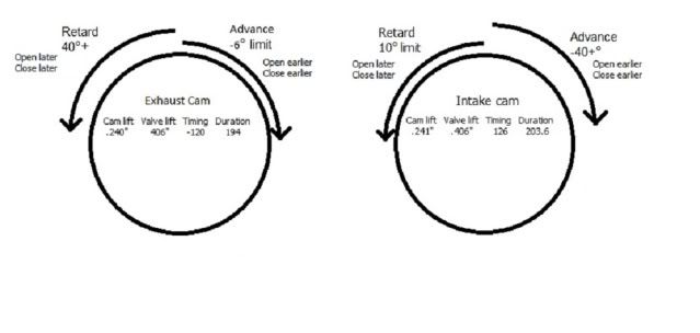
For higher mpg's, you want to reduce pumping losses. You do that by lowering dynamic compression. The way that's done is by retarding the exhaust and advancing the intake timing. That increases overlap and basically lets some amount of exhaust back into the chamber. This also lowers egt's.
For low end power, you want to advance intake and exhaust timing. That raises dynamic compression.
For top end power (turbo), you want to retard intake and exhaust timing. Later intake valve closing gives the pressurized intake charge more time to fill the cylinder, even if it's into the compression stroke a little bit. If you've got 30psi boost pushing the intake charge in, the piston is gonna have to go up to the point of building 30psi before it could even start pushing the charge back into the intake. Retarding exhaust timing lets the piston start pushing the exhaust out a little before it opens the exhaust valve, which helps if the backpressure in the exhaust manifold is high. (small turbo) Retarding both intake and exhaust at high rpm's lowers dynamic compression again and lets the motor rev out easier. (I learned that on the LS motors with VVT, advance the cam too far on the top end and it simply will not rev out, and knock like crazy! High compression is good down low, it's not so good up high.)
Light loads, if you want power, reduce overlap by advancing exhaust and retarding intake a little bit. If you want mileage, go the other direction, increase overlap and retard the intake and exhaust a ton. The high numbers around freeway cruise in the LNF (and most every other VVT engine without an EGR valve) is for mileage. If you want power, take away a bunch of the exhaust retard, you can leave some of the intake advance, but watch the overlap. The secret here is keep the big overlap RIGHT AT freeway cruise rpm and loads, then close up the overlap right away when rpm's or load starts going up. That way you get high freeway mpg's but a little more on the pedal and it's pulling hard. My freeway cruise is right around 2500rpm and 50% load, so that's where I have the big exhaust retard and intake advance. Right out of those cells and I'm back into power mode. Tricky part here is making sure you don't have too big of a mountain in your cam timing maps. You can make up for some of the dip in power as you go through that mountain with the other torque/throttle control tables. If the power has a low spot on a normal accel, just bump up the throttle in that spot.
Hope that helps, it's midnight and I might have gotten something in there backwards! To throw another monkey wrench in all this, if you're making big cam timing changes, you better be adjusting your ign timing and injector timing tables too. Look at the injection timing tables and you'll see numbers in there that were put in to match cam numbers.
One more thing, if you want to see what effect a table has, GO BIG! Meaning don't change a cam timing cell from 36 to 32 and expect to "feel" the difference. Take those cells from 36 down to 10 or so just so you can see what it does in actual driving. Same with what you guys were talking about with the torque management settings, if it's at 100% in a certain row or cell, drop it to 50% and I'm betting you'll be able to see if it does anything or not. If it doesn't do anything, drop it to 10%, if it still doesn't do anything it's a table that doesn't work or something else is over-riding it. There's a few of those.


 Reply With Quote