Results 1 to 18 of 18

Thread: Question: Tuning Spark

  1. #1

    Question: Tuning Spark

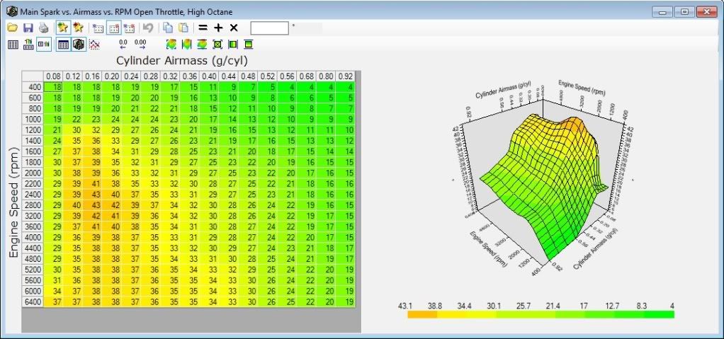
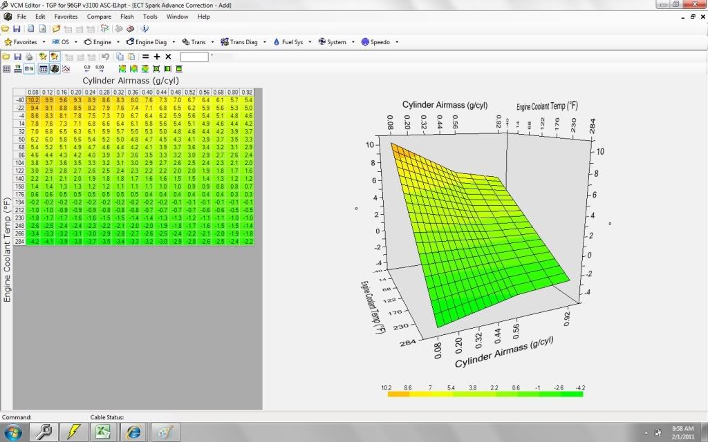
    Why are nearly all spark maps level at high load/rpm?

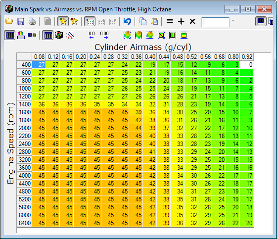
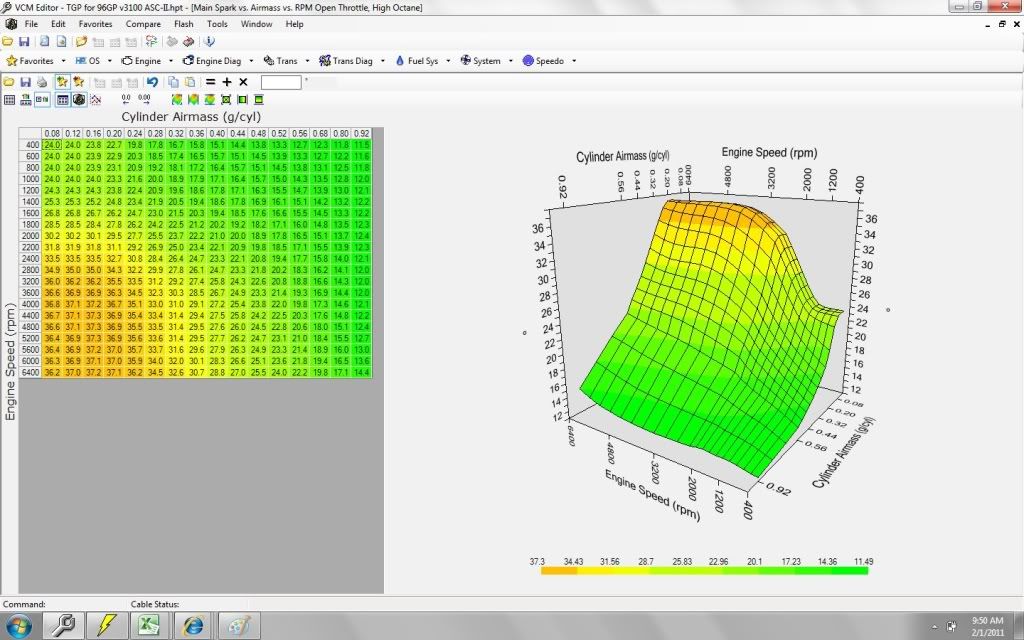
    My GP Spark Map ranges from 17-20 degrees advance at 0.92 g/cyl (3600-5600 RPM). This seems just fine except for the math.

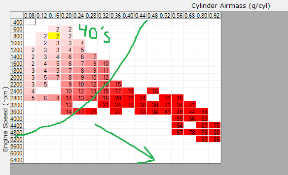
    As RPMS increase the flame speed still remains the same resulting in timing having to become gradually more advanced as rpm's rise. The math doesn't add up.

    Point example:
    3600 rpm at 18* BTDC advance with optimal peak pressure at 12* ATDC. Rotating 30 degrees at that rpm takes 1.388889 ms. So this is a good reference time for burn time to peak pressure, 1.388889 ms. As I know my engine runs great at these settings.

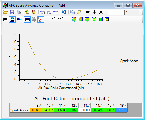
    But at 5200 rpms one needs an advance of 31.33 degrees BTDC to hit 12* ATDC in 1.388 ms. As the flame front takes roughly about 1.3 ms to reach the piston at an AFR of 13.7:1

    This is what confuses me about the Stock Spark Maps. Are these maps that generalized and thus horribly inaccurate or .....what am I missing?

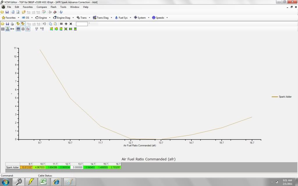
    I even calculated the speed of flame front per AFR.
    10:1 = 330 mm per sec
    11:1 = 380 mm per sec
    12:1 = 413 mm per sec
    13:1 = 425 mm per sec
    14:1 = 423 mm per sec
    15:1 = 415 mm per sec
    16:1 = 402 mm per sec


    What about airmass and its effects on flame front speed?
    96 Grand Prix 3100 5-Speed Turbo

    T04E 50-Trim Internal WG @ 12psi, Intercooled | HM-282 5 Speed w/ EP LSD | Spec 3 Clutch w/ HTOB Port-Polish-Deshrouded Heads | Ported LIM | 36 lb/hr L67 Injectors @ 65 rail psi | Walbro 255 Pump | 2.5" Custom Exhaust w/ Dual Flowmaster 40s | 97 PCM w/ 2 Bar Map HPTuned | Synchronic BOV | 220A HO ALT | ARP Rods/Main/Pan/Studs/Flywheel Bolts

    Gauges: Wideband (data logging), EGT, Boost/Vac, Turbo Oil Press, Oil Temp

  2. #2
    You are crazy haha. Very smart dood.... anyway, I went about creating my own spark table from scratch. I didn't use any crazy math like you but I knew that timing should increase with rpm but decrease with air density. If you're interested here's what it looks like:

  3. #3
    edit update: I found a document from NASA and the USAF as per study of OttoCycle Engines and the Introduction of Hydrogen. It has a LOAD of information hard to find else where. As example, flame speeds at 140psi. The research is offbeat what most of us are doing but standard gasoline is used as a constant.

    link
    end

    Yes, interesting to see others work. Actually your spark map looks a lot like mine in rows 0.52~0.92 g/cyl.
    I remember posting a map for ignition offset per AFR. It was off a bit, here is the new map.


    I tested in my pcm several times and I noticed no ill results so far. My idle variance seemed to improve slightly. But that was all so far. However, the spark map needs better refining at high load/boost in order for me to notice any gain or losses in power.

    I did the math on this and according to the AFR this map will adjust and correct the difference of flame front speed. It is accurate from 800-6400rpm's (tested several curves and this works best)

    Maybe the only confirmation I will get is a street test. Hmmm, I guess I am going to devise a plan to increase spark gently towards the goal spark map in question. If it works, more torque/hp, I will post it up. But my heads are unique now as I deshrouded the valves and polished the area.

    Yeah Oakleaf, I'm a crazy one. Math never lies if the operator uses it properly. I bet having a spark offset vs. boost pressure would really help smooth things out. Eventually I want to calculate the effects on flame front speed vs IAT.
    Last edited by TGP-37; 01-29-2011 at 10:43 AM.
    96 Grand Prix 3100 5-Speed Turbo

    T04E 50-Trim Internal WG @ 12psi, Intercooled | HM-282 5 Speed w/ EP LSD | Spec 3 Clutch w/ HTOB Port-Polish-Deshrouded Heads | Ported LIM | 36 lb/hr L67 Injectors @ 65 rail psi | Walbro 255 Pump | 2.5" Custom Exhaust w/ Dual Flowmaster 40s | 97 PCM w/ 2 Bar Map HPTuned | Synchronic BOV | 220A HO ALT | ARP Rods/Main/Pan/Studs/Flywheel Bolts

    Gauges: Wideband (data logging), EGT, Boost/Vac, Turbo Oil Press, Oil Temp

  4. #4
    So how does your GFS table look then, if you are adding spark with the AFR table like this? It would seem to me that the GFS table would be rather static/without variation? I was told to make the .92 g/cyl side look like it does from 4400 - 6400 from someone at ZZP that does a lot of dyno testing. Apparently the engine makes the best power with a curve like that.

    It does bother me that I'm sort of shooting in the dark with the spark table though. I like that you're using math to actually come up with optimal values. I followed the trend that the engine follows when accelerating to make that timing table.

    Made this a while ago to help figure out the trend...

  5. #5
    Senior Tuner
    Join Date
    Dec 2004
    Location
    Laurel, MD
    Posts
    1,020
    TGP, what is your formula for flame front if you're not using airmass? AFR is only one of the variables, airmass in this case affects the flame front as well due to varied compression of air/fuel molecules.

  6. #6
    Quote Originally Posted by redhardsupra View Post
    TGP, what is your formula for flame front if you're not using airmass? AFR is only one of the variables, airmass in this case affects the flame front as well due to varied compression of air/fuel molecules.
    I went to Walmart, but could not find a Timing Calculator.

  7. #7
    Quote Originally Posted by redhardsupra View Post
    TGP, what is your formula for flame front if you're not using airmass? AFR is only one of the variables, airmass in this case affects the flame front as well due to varied compression of air/fuel molecules.
    I am putting data together in several different fronts and then hoping to bring those fronts together.

    I.E.- Timing curves for AFR, kPa and RPM. The speed of flame front will alter with AFR, naturally, AND will be altered with manifold pressure. Get these values to be true and collaborate with RPM.

    There is no specific formula rather I am putting a large puzzle together.

    The AFR curve was carefully designed from 2 different studies regarding flame front speed. One was in a tube and the speed of air feeding the flame was the speed of the flame front, since the flame front was stabilized (not moving forward or backwards). This gave me solid data on the speed from spark under specific AFR. THIS isn't complete yet as I need to incorporate the effects of manifold pressure on the speed of flame front. The other test data was released from NASA years ago. Both studies reveal identical results.

    Once I can get those two correct, adjusting for RPM will be easy. I have a spare cylinder head used to measure precise distances from spark to head gasket line. From there I can get the distance to the dish in the piston.

    But until then I am using a known good spark at a specific RPM and AFR. Two I can confirm are (13.5 AFR, 800 RPM, 20inHg vac at 18*BTDC) and (11.0 AFR, 3600RPM, @5-8psi at 18* BTDC) Both have the same degree advance but share different operation characteristics.

    Sorry if I am confusing, I often confuse myself until I get it. SOmetimes hours of thought before the light bulb goes pop.

    I test the results with calculating data. Injector pulse width is a good indicator of performance increase or decrease. I use excel religiously on the fly, I have no specific system yet.

    The AFR curve is perfect mathematically and tested fine so far in the vehicle driving around. I even feel a better pull with that flashed in.

    OAKLEAF, thanks for the info on the spark map. SInce the region you expressed was dyno tuned it holds strong weight IMHO. And it isn't to far off from my spark map. I gradually got to this point from Theoretical Torque Maximum as my starting point. I am also partially blind as my math doesn't have verification yet.

    I will post up later if I come across something. I will be spending some time today figuring this out more.

    Anyone know where I can get a spark plug device to measure peak cylinder pressures? That would change everything and give my math a solid verifying. From there I can achieve spark perfection.

    I will not stop until the Peak Pressure lands on 12* ATDC consistently. Or whatever *ATDC is best power. I am assuming lower RPM might have greater power further from TDC but not sure yet.

    Part of this project is being able to tune w/o a dyno. When I do eventually get a dyno tune well see how close I was getting.
    96 Grand Prix 3100 5-Speed Turbo

    T04E 50-Trim Internal WG @ 12psi, Intercooled | HM-282 5 Speed w/ EP LSD | Spec 3 Clutch w/ HTOB Port-Polish-Deshrouded Heads | Ported LIM | 36 lb/hr L67 Injectors @ 65 rail psi | Walbro 255 Pump | 2.5" Custom Exhaust w/ Dual Flowmaster 40s | 97 PCM w/ 2 Bar Map HPTuned | Synchronic BOV | 220A HO ALT | ARP Rods/Main/Pan/Studs/Flywheel Bolts

    Gauges: Wideband (data logging), EGT, Boost/Vac, Turbo Oil Press, Oil Temp

  8. #8
    Quote Originally Posted by oakleafresin View Post
    So how does your GFS table look then, if you are adding spark with the AFR table like this? It would seem to me that the GFS table would be rather static/without variation? I was told to make the .92 g/cyl side look like it does from 4400 - 6400 from someone at ZZP that does a lot of dyno testing. Apparently the engine makes the best power with a curve like that.

    It does bother me that I'm sort of shooting in the dark with the spark table though. I like that you're using math to actually come up with optimal values. I followed the trend that the engine follows when accelerating to make that timing table.

    Made this a while ago to help figure out the trend...
    btw, for those who will say, just get it Dyno Tuned, I agree. But this project is to see just how well a tune one can achieve with HPT and the Street. I have faith in this product.

    Knowing the spark map from 4400-6400 is dyno tested and true I will try some calculation utilizing that data as a known good point.

    I'm not sure if I understand the Table you just posted. ???? vs RPM/Airmass?


    Our Spark Maps aren't so different in the boosted regions....


    This map has been some help designing a spark table (edit: this table specifically was for the OL Fuel Adder, RPM table differences)...though probably slightly off from your vehicle, the concept remains. Ignore the typo at idle, lol I don't idle at 2PSI...lol
    Last edited by TGP-37; 01-30-2011 at 12:38 PM.
    96 Grand Prix 3100 5-Speed Turbo

    T04E 50-Trim Internal WG @ 12psi, Intercooled | HM-282 5 Speed w/ EP LSD | Spec 3 Clutch w/ HTOB Port-Polish-Deshrouded Heads | Ported LIM | 36 lb/hr L67 Injectors @ 65 rail psi | Walbro 255 Pump | 2.5" Custom Exhaust w/ Dual Flowmaster 40s | 97 PCM w/ 2 Bar Map HPTuned | Synchronic BOV | 220A HO ALT | ARP Rods/Main/Pan/Studs/Flywheel Bolts

    Gauges: Wideband (data logging), EGT, Boost/Vac, Turbo Oil Press, Oil Temp

  9. #9
    I think I have a better way of explaining my madness here....and what it is exactly I am accomplishing. But I need help of like minded people and share the data.

    Picture this, every car has that 'sweet spot' where the power in the wheels is at its best. It's pulling hard, the torque is there, no misfires, ect, ect.

    Now, imagine freeze frame right at that moment. From here on we want to alter the spark exactly as physics allows and no different. So this point in time is our grand reference. It is a known good spark, afr, ect.

    So as the airmass in the cylinders rise there is more pressure at the point of combustion. But exactly how much it effects the flame fronts speed is what I want to know. Once this data is obtained then the spark table can be altered accordingly from the grand reference point the 'sweet spot' reference.

    And then also allow the same for AFR fluctuations. Which I have completed and is ready.

    With a dedicated approach I believe I can pull this off and maintain the optimal spark degree from a known good setting. So where ever the peak pressure is occuring, 10*-20* ATDC it doesn't matter. We are riding the wave from a specific point of optimal performance.
    96 Grand Prix 3100 5-Speed Turbo

    T04E 50-Trim Internal WG @ 12psi, Intercooled | HM-282 5 Speed w/ EP LSD | Spec 3 Clutch w/ HTOB Port-Polish-Deshrouded Heads | Ported LIM | 36 lb/hr L67 Injectors @ 65 rail psi | Walbro 255 Pump | 2.5" Custom Exhaust w/ Dual Flowmaster 40s | 97 PCM w/ 2 Bar Map HPTuned | Synchronic BOV | 220A HO ALT | ARP Rods/Main/Pan/Studs/Flywheel Bolts

    Gauges: Wideband (data logging), EGT, Boost/Vac, Turbo Oil Press, Oil Temp

  10. #10
    Advanced Tuner MikeGyver's Avatar
    Join Date
    Feb 2006
    Location
    Suburban Chicago
    Posts
    268
    I think that the most important factor of flame front speed that you're leaving out is turbulence. There's a reason that our heads have squish bands on opposing sides of the combustion chambers, you know.
    2000 GMC 2500 2-bar SD
    Stock LM7, LTs, TBSS intake manifold

  11. #11
    Quote Originally Posted by MikeGyver View Post
    I think that the most important factor of flame front speed that you're leaving out is turbulence. There's a reason that our heads have squish bands on opposing sides of the combustion chambers, you know.
    Yeah, I realize the factor of turbulance, the most chaotic factor of all. This is why I am using a known good spot determined from logs. And adjust spark from that good spot. I read a good, long article about turbulence and how the wrinkle in the surface front makes the expansion slow down due to increase in surface area. So in a way, the difference from Optimal Theoretical Spark Degree versus Optimal Real Life Spark Degree could respresent the factor of turbulence. If all values are accounted for except for one, the difference will be that one value left out.

    So if I am getting the best acceleration/torque/ect at X RPM with X AFR then the spark curve from that point should continue the optimal performance.

    Example, if my engine runs best at 3600 RPM with 22* IGN then the following spark tables down the RPM band should reflect that specific point.

    Like the speed of the flame front vs afr is hard to pin point the specific cm/sec value but getting the curve itself is much easier. So that is what I did for Spark vs AFR and it seems to work so far. But I have much more testing before I declare improvement with such a Spark vs AFR Table.

    So in a way I am creating a spark table curve w/o a specific spark degree. Then scaling up or down and eventually hit the right spot. And if the spark curve is correct then optimal performance should occur through out all cells.
    96 Grand Prix 3100 5-Speed Turbo

    T04E 50-Trim Internal WG @ 12psi, Intercooled | HM-282 5 Speed w/ EP LSD | Spec 3 Clutch w/ HTOB Port-Polish-Deshrouded Heads | Ported LIM | 36 lb/hr L67 Injectors @ 65 rail psi | Walbro 255 Pump | 2.5" Custom Exhaust w/ Dual Flowmaster 40s | 97 PCM w/ 2 Bar Map HPTuned | Synchronic BOV | 220A HO ALT | ARP Rods/Main/Pan/Studs/Flywheel Bolts

    Gauges: Wideband (data logging), EGT, Boost/Vac, Turbo Oil Press, Oil Temp

  12. #12
    I present these tables for advise, opinions, ect. Hoping others may have some insight.

    Okay, after much mind bending, lots and lots of reading, excel crunching and coffee chugging I have my new spark design.

    It hasn't been tested yet so use at your own risk.

    Brief Description how these values were obtained.

    High Octane: I acquired spark curves for RPM and Vac seperately and merged together for the base. Since the AFR vs Spark table will add roughly 5 degrees at WOT (AFR of 10.7) the Base needed to be adjusted. A histogram of my AFR provided a solid adjustment value. So when the AFR hits 10.7 the Base High Octane + AFR Adjustments will add up to the spark curve provided by Oakleafresin (I tested in my car and it worked great, btw thanks)

    Low Octane: Compared the ratio difference across several stock files to achieve a Low Octane Map that would resemble a true stock Low Octane Map.

    AFR vs Spark: Used results from several studies and incorporated the appropriate spark degree offset.

    IAT vs Spark: This table adjusts the spark according to density. (491.67/IAT+451.67)*0.0808 = Density lb/ft3. The speed of combustion is assumed to scale in proportion to air density. Denser = Faster, Vac = Slower.

    But this table is also used to protect from detonation at higher IAT's. So the stock IAT spark adjustments were basically retained.

    ECT vs Spark: Generic stock values leveled across Airmass with the exception of reducing the adjustment by 50% at higher Airmass under the assumption greater airflow is less effected by engine block temps due to less time being exposed to the iron/aluminum walls from higher velocities.
    ***note: I will probably adjust this table soon. I decided to pursue the physics of Heat Conductivity between Air at various Airmass vs ECT. The Airmass should roughly represent airflow which will roughly give the amount of time the aircharge is in contact with the aluminum intake setup. With those two variables I should be able to know exactly how much ECT will alter the IAT all the way to the intake valve.


    Last edited by TGP-37; 02-01-2011 at 12:11 PM.
    96 Grand Prix 3100 5-Speed Turbo

    T04E 50-Trim Internal WG @ 12psi, Intercooled | HM-282 5 Speed w/ EP LSD | Spec 3 Clutch w/ HTOB Port-Polish-Deshrouded Heads | Ported LIM | 36 lb/hr L67 Injectors @ 65 rail psi | Walbro 255 Pump | 2.5" Custom Exhaust w/ Dual Flowmaster 40s | 97 PCM w/ 2 Bar Map HPTuned | Synchronic BOV | 220A HO ALT | ARP Rods/Main/Pan/Studs/Flywheel Bolts

    Gauges: Wideband (data logging), EGT, Boost/Vac, Turbo Oil Press, Oil Temp

  13. #13
    Tuner
    Join Date
    Dec 2005
    Location
    Verona, WI
    Posts
    144
    The one thing you are forgetting is that the engine's air pumping efficiency changes through out the RPM range so just because RPM is increasing doesn't mean that the air load in the cylinder is greater. What you should notice is that you have the least amount of timing advance at peak torque. I too have thought about the flame front speed and increasing your timing advance xx° for every 100 rpm higher...but if the engine efficiency is lower at 6100 RPM compared to 6000 RPM, then you may actually need more timing at 6100 because there is less air that reached the cylinder. So it's a balance between the flame front speed and actual air load. If you look at most spark tables that's why it also references g/cyl and if you do a WOT pull and log a scan in the timing map you may actually see that your engine is registering fewer g/cyl of air at 6000 RPM than it does at 5500 RPM, depending on your engines efficiency curve.

  14. #14
    Advanced Tuner Phantom's Avatar
    Join Date
    Jan 2008
    Location
    Louisville KY
    Posts
    200
    I am wondering how this project has been going and also wanted to ask, why do you not have the AFR VS Spark table set using 14.7:1 as the bottom of the curve? It seems like you use that set to 0 and scale the other values to match such as subtracting 0.549 from all values on that table then add 0.549 to the main spark table to bring it back to what you are running now.

    02 VW Golf

    98 Bonneville SSE
    03 Grandprix GT
    EcoModder

  15. #15
    Quote Originally Posted by Phantom View Post
    I am wondering how this project has been going and also wanted to ask, why do you not have the AFR VS Spark table set using 14.7:1 as the bottom of the curve? It seems like you use that set to 0 and scale the other values to match such as subtracting 0.549 from all values on that table then add 0.549 to the main spark table to bring it back to what you are running now.
    I see what you mean. The modifier was designed to add spark for anything less then the fastest AFR possible, 13.2-13.4.

    You could subtract just enough to make 14.7 zero. I just like to keep things simple. Computers can calculate positive numbers MUCH faster then negatives. Probably nothing we can notice, just some programming habits.

    All these tables are still in the rough design stage. I wouldn't slap them on and go, that might be dangerous, lol.

    I am considering a method of data logging peak pressure. Until then, I can't do a whole lot more. Except for some physics I plan to dive into. I want to calculate how much heat is transfered into the LIM versus surface area, transfer through material cross-sectional area, the works. I want to get a very precise calculation difference of intake temps past the IAT.

    If I had the money, I would LOVE to reverse engineer 6 MAF sensors and attach the sensor wires to the Plenum/LIM gasket and place the IAT just ahead of that in the Runners. I'm not sure how to run 6 MAF's, 1 for each cylinder. But that would be bad @ss!

    Imagine this, 6 MAF, 6 IAT, 6 Widebands and 6 EGT's and a controller to adjust spark degree referrencing peak pressure sensors built into the spark plug. It would be a vehicle controller from GOD, lol. Maybe I should start designing my own PCM.
    Last edited by TGP-37; 06-05-2011 at 05:09 PM.
    96 Grand Prix 3100 5-Speed Turbo

    T04E 50-Trim Internal WG @ 12psi, Intercooled | HM-282 5 Speed w/ EP LSD | Spec 3 Clutch w/ HTOB Port-Polish-Deshrouded Heads | Ported LIM | 36 lb/hr L67 Injectors @ 65 rail psi | Walbro 255 Pump | 2.5" Custom Exhaust w/ Dual Flowmaster 40s | 97 PCM w/ 2 Bar Map HPTuned | Synchronic BOV | 220A HO ALT | ARP Rods/Main/Pan/Studs/Flywheel Bolts

    Gauges: Wideband (data logging), EGT, Boost/Vac, Turbo Oil Press, Oil Temp

  16. #16
    Quote Originally Posted by MikeGyver View Post
    I think that the most important factor of flame front speed that you're leaving out is turbulence. There's a reason that our heads have squish bands on opposing sides of the combustion chambers, you know.
    It did not dawn on me what you said exactly but I just got it re-reading this thread.

    I want to recreate the combustion process step by step EXACTLY as physics can explain it. Which means I need to find a formula to express quench, or atleast find the ratio it increases the flame propogation speed.

    If everything is accounted for properly, then a perfect spark map should be attainable. Complete with margin of error tables as well for adjustment.

    THAT is going to be one long project.

    Thanks
    96 Grand Prix 3100 5-Speed Turbo

    T04E 50-Trim Internal WG @ 12psi, Intercooled | HM-282 5 Speed w/ EP LSD | Spec 3 Clutch w/ HTOB Port-Polish-Deshrouded Heads | Ported LIM | 36 lb/hr L67 Injectors @ 65 rail psi | Walbro 255 Pump | 2.5" Custom Exhaust w/ Dual Flowmaster 40s | 97 PCM w/ 2 Bar Map HPTuned | Synchronic BOV | 220A HO ALT | ARP Rods/Main/Pan/Studs/Flywheel Bolts

    Gauges: Wideband (data logging), EGT, Boost/Vac, Turbo Oil Press, Oil Temp

  17. #17
    Tuner in Training
    Join Date
    Oct 2009
    Posts
    27
    I see someone mentioned looking at scan logs and seeing g/cyl higher or lower. How do you set up your scanner to show where you are in g/cyl?

    I am having fits with timing and KR from 3500-4500, (peak TQ) It is also where the boost ramps up pretty quick, so I was thinking it's mostly burst-knock. The attack rate and recover rate have been massaged slightly to no avail. I am still seeing 4-5degKR. The KR brings timing down to 15deg, so I put in 15 from 400mg/cyl up from 3000-6400. And I have zero'd all the other timing tables, ECT, IAT, etc. It is commanding 19-20deg where I think I have 15.

    How do I scna for g/cyl??? That sure would help alot.

  18. #18
    Advanced Tuner
    Join Date
    Sep 2009
    Location
    Angola NY, (Buffalo)
    Posts
    202
    Just watching...
    The Regal has been laid to rest..... rust
    Now have an 06 Lucerne with the 3.8 and wishing HPT would cover that car
    Loved my 2001 Buick Regal GS.
    With more than 334,000K, 3.4 & 3.6 pulley, Change stats and pulleys with the seasons, Upgraded grounds & power wire, Volt booster, Caspers timing commander(AKA happy knob), Spectra intake-fender wall, PLog, 3" DP & 2.5 exhaust, HPTunner 12" Impala duel piston front brakes, New trans,GMPP suspension... yada, yada...