I've wired up the AEM analog output (White) to the OEM signal wire (purple) using the existing down stream harness not being used.
Looking for proper custom PID formula that converts O2 B1S2 mv into AFR.


I've wired up the AEM analog output (White) to the OEM signal wire (purple) using the existing down stream harness not being used.
Looking for proper custom PID formula that converts O2 B1S2 mv into AFR.
99 Dark Metallic Bronzemist SSEi, 187K, S3, P&P GenV, 3.4MPS, N*TB & LQ4, SLP Headers, Cat & EGR Delete, Hockey puck TA mount, Solid Trans/Motor mount, KYB fronts, MSD Wires&Coils, TRE-340, Thrasher CAI w/ 9" K&N, C-Ya Shift Kit, Hayden Trans cooler.
Are you sure the narrowband sensor is a +/-5v input? I would have thought it was 1v :/
Anyway, if you want to figure out what the PID.### is, click the ? mark above where the "function" goes.
Not sure at all. I've got the WB installed and working on the gauge in the Pod. The AEM has a serial output and an analog output wire. I connected the AEM analog output (White) to the OEM signal wire (purple) using the existing downstream O2 not being used. The AEM analog output connects to any auxiliary unit that accepts a 0-5 volt input.Originally Posted by oakleafresin

I sensor ([PID .21] O2 Voltage B1S2 (SAE)) captures mv.
EDIT: In doing some reflecting... if 1 millivolt = 0.001 volts, then couldn't the formula be: ([SENS .21]*.001)/.5+10 ?
Last edited by 99ssei; 01-15-2011 at 10:46 PM.
99 Dark Metallic Bronzemist SSEi, 187K, S3, P&P GenV, 3.4MPS, N*TB & LQ4, SLP Headers, Cat & EGR Delete, Hockey puck TA mount, Solid Trans/Motor mount, KYB fronts, MSD Wires&Coils, TRE-340, Thrasher CAI w/ 9" K&N, C-Ya Shift Kit, Hayden Trans cooler.
This is too funny... I was thinking of the #2 as well, but not sure how you would convert it
Here's a scan with the NB analog output connected to #2.
I can't view the custom PID formula w/o connecting to PCM (standard).
99 Dark Metallic Bronzemist SSEi, 187K, S3, P&P GenV, 3.4MPS, N*TB & LQ4, SLP Headers, Cat & EGR Delete, Hockey puck TA mount, Solid Trans/Motor mount, KYB fronts, MSD Wires&Coils, TRE-340, Thrasher CAI w/ 9" K&N, C-Ya Shift Kit, Hayden Trans cooler.
I was thinking about it... if the voltage supplied by the WB is 0-5v, and the rear O2 is measured in mv (or 0-1v), the conversion would be PID.21*.001 to get the votage in a range of 0-10v, then the formula would be ([PID.21]*0.001)/0.1)+10 ?
I ran this through scan data in excel and mathematically it makes sense.
Can someone check my math?
99 Dark Metallic Bronzemist SSEi, 187K, S3, P&P GenV, 3.4MPS, N*TB & LQ4, SLP Headers, Cat & EGR Delete, Hockey puck TA mount, Solid Trans/Motor mount, KYB fronts, MSD Wires&Coils, TRE-340, Thrasher CAI w/ 9" K&N, C-Ya Shift Kit, Hayden Trans cooler.
Found it! The AEM version I have has switchable analog output voltage!
Configuring Calibration Outputs
If a different O2 sensor calibration is desired, the AEM calibration can be changed to one of three available. The AEM default position is (P0) if an AFR Gauge was purchased and (P1) if a Lambda Gauge was purchased. These settings implement a linear calibration with the most useful voltage range possible (0-5V). The AFR calibration (P2) is linear and similar to (P1) with a slightly smaller voltage range (1-2V). The AFR calibration (P3) emulates the Autronic Wideband O2 Sensor calibration (0-1V). The AFR calibration (P4) emulates a non-linear Nernst Cell calibration (0-1V). Refer to the Table and Graph for specific calibration details.
I read in another thread that Nernst sensor cell is what we all call a narrowband 0-1V sensor.
See Page 8
http://www.aemelectronics.com/Images...%2030-4100.pdf
99 Dark Metallic Bronzemist SSEi, 187K, S3, P&P GenV, 3.4MPS, N*TB & LQ4, SLP Headers, Cat & EGR Delete, Hockey puck TA mount, Solid Trans/Motor mount, KYB fronts, MSD Wires&Coils, TRE-340, Thrasher CAI w/ 9" K&N, C-Ya Shift Kit, Hayden Trans cooler.
So is it possible or has anyone tried it with the autometer wideband's??? I'm looking at the 5778 and here is a link to the instructions. http://www.autometer.com/productPDF/1143A.pdf The way i understand it i should be able to scale the voltage down with the bgd range setting. Can anyone confirm it.
Thanks in advance for any help.
Edit: I might end up with the aem anyway after reading there instructions again it looks much easier to set up and the reason i was going to go with the autometer anyway was so it matched my boost gauge but i'm going to mount it in a different location now i think.
Last edited by bstromback; 03-04-2011 at 09:36 PM.
It says the output voltage can be changed from 0-5v down to 0-1v however, going through the O2B2 sensor, I haven't found the right formula yet. I have not thrown a volt meter on the output to verify yet either.
99 Dark Metallic Bronzemist SSEi, 187K, S3, P&P GenV, 3.4MPS, N*TB & LQ4, SLP Headers, Cat & EGR Delete, Hockey puck TA mount, Solid Trans/Motor mount, KYB fronts, MSD Wires&Coils, TRE-340, Thrasher CAI w/ 9" K&N, C-Ya Shift Kit, Hayden Trans cooler.
Did you ever get this figured out???? I hooked up my aem wideband today through the b1s2 i see it on my gensisys scanner but i don't see it on hpt when i change the chart to graph sensor 2.
Anyone have any ideas.
2005 Grand Prix Comp G, 180 tstat, KN intake, 3.6 pulley, pacesetter headers
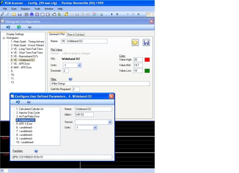
You have to add a user defined PID. Go to your primary table, right click, insert, under "user defined" choose Configure User Defined, choose a table (I think one has WB as a default).
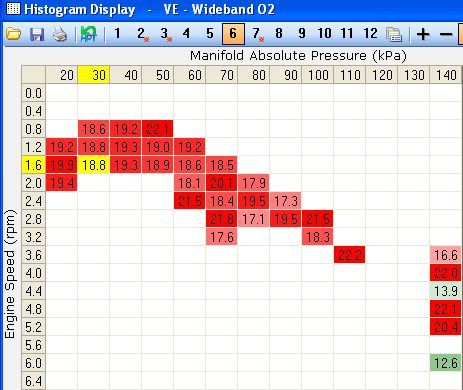
Here's a pic of how mine is set up, however, I have not been able to validate the formula. When I check out the scan data (export to excel) I see that my commanded AFR is 11.5 and I know I'm seeing 11.2 - 11.7 @ WOT, but the B1S2 is showing an average of 464 mv, which using my formula is 13.9 AFR.
When commanded is 14.7, B1S2 (SAE) is showing an average of 456 mv and 13.88 using the formula (WB sensor/1000)/(1/8.5)+10. This formula is from another thread. I'm still lost here.
99 Dark Metallic Bronzemist SSEi, 187K, S3, P&P GenV, 3.4MPS, N*TB & LQ4, SLP Headers, Cat & EGR Delete, Hockey puck TA mount, Solid Trans/Motor mount, KYB fronts, MSD Wires&Coils, TRE-340, Thrasher CAI w/ 9" K&N, C-Ya Shift Kit, Hayden Trans cooler.
Well i sorta figured out why i couldn't see it on my scanner but not sure why it happened, i reflashed my ecm once to renable a couple 02 sensor codes and that didn't work so i removed them and reflashed it again and suddenly it worked. Now the only problem I have is it's reading about 100 mv to high.
Also to make it work in the histogram I have to use pid.6101 now i just need to figure out the formula part of it. Also i have my gauge in p3 mode cause it looks like it will give a smoother voltage change.
Last edited by bstromback; 03-22-2011 at 09:05 AM. Reason: update
2005 Grand Prix Comp G, 180 tstat, KN intake, 3.6 pulley, pacesetter headers
Did you ever get your wideband working??? I'm just wondering how that formula worked out for you????
2005 Grand Prix Comp G, 180 tstat, KN intake, 3.6 pulley, pacesetter headers
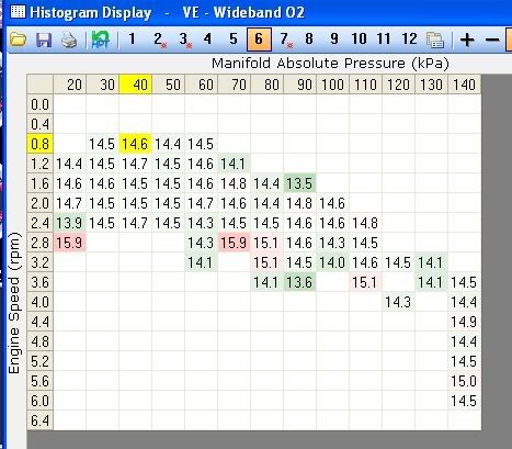
Not quite.... here's where I'm at. I switched to the PO3 setting on the AEM. I'm working with a guru on another forum. I was hoping the experts here would chime in, but haven't seen any posts...
[PID.21] = 02 Voltage B1S2 (SAE), which when exported to CSV is in mv...
Using this formula = (([PID.21]/1000)*10)+10
After re-loading the old data, here's what the histo looks like:
Any suggestions would be appreciated.
99 Dark Metallic Bronzemist SSEi, 187K, S3, P&P GenV, 3.4MPS, N*TB & LQ4, SLP Headers, Cat & EGR Delete, Hockey puck TA mount, Solid Trans/Motor mount, KYB fronts, MSD Wires&Coils, TRE-340, Thrasher CAI w/ 9" K&N, C-Ya Shift Kit, Hayden Trans cooler.
I'm not 100% sure but I think i see a couple problems with the info your using but i could be wrong. One our wideband is only from 10 - 18.5 and the voltage range on p3 is only 0 to 425mv not 0 - 1v and according to the instructions stoich on p3 is around 238 mv the directions actually show 238mv as 14.75 so it's probably a smidge lower.
Have you ever compared your voltage output to what the gauge says i'm having a problem with mine reading about 100mv higher on p3 so when my gauge shows 14.7 the output is 330mv I tried some of the other settings and they were all off too just don't remember how much
2005 Grand Prix Comp G, 180 tstat, KN intake, 3.6 pulley, pacesetter headers
Interesting...according to AEM user guide (link above) it says, "The AFR calibration (P3) emulates the Autronic Wideband O2 Sensor calibration (0-1V)." But the graph shows P3 doesn't go above .5v.... I'll try going back to the P4 setting and try again.
I also saw on the specs page that the gauge "Measuring Range" is 0.751 to 1.143 Lambda. If i converted it correctly, that's 11.04:1 to 16.80:1... but they have a table that shows 0v = 10.00:1 and 4.99v = 19.98:1...on AEM's website, the features says:
# 0-5v analog output Gasoline values from 10 to 20:1 AFR
# 0-5v analog output E85 values from 6.6 to 13.2 AFR
# 0-5v analog output Ethanol values from 6.14 to 12.3:1 AFR
# 0-5v analog output Methanol values from 4.4 to 8.8:1 AFR
# 0-5v analog output Lambda values from .68 to 1.36:1
that doesn't make any sense....
99 Dark Metallic Bronzemist SSEi, 187K, S3, P&P GenV, 3.4MPS, N*TB & LQ4, SLP Headers, Cat & EGR Delete, Hockey puck TA mount, Solid Trans/Motor mount, KYB fronts, MSD Wires&Coils, TRE-340, Thrasher CAI w/ 9" K&N, C-Ya Shift Kit, Hayden Trans cooler.
Try this one out and let me know how it works out for you it won't work for me cause of my output being off but i tested it out by comparing voltages and what not and it seems like it should work for anyone and everyone running a AEM wideband on the p3 setting.
(([PID.21]/425)*8.5)+10
2005 Grand Prix Comp G, 180 tstat, KN intake, 3.6 pulley, pacesetter headers
You are using the info for the aem EMS go here and download the instructions.
http://forum.aempower.com/forum/inde...c,21559.0.html and go to page 9 of the instructions.
2005 Grand Prix Comp G, 180 tstat, KN intake, 3.6 pulley, pacesetter headers
Here's the formula you posted on P3 setting:
(([PID.21]/425)*8.5)+10
I'll switch the gauge to P4 and post those soon (gotta pull the gauge out to make the change).
99 Dark Metallic Bronzemist SSEi, 187K, S3, P&P GenV, 3.4MPS, N*TB & LQ4, SLP Headers, Cat & EGR Delete, Hockey puck TA mount, Solid Trans/Motor mount, KYB fronts, MSD Wires&Coils, TRE-340, Thrasher CAI w/ 9" K&N, C-Ya Shift Kit, Hayden Trans cooler.
Are u sure your not on p4 now what kind of a voltage range are u seeing while scanning?? When the gauge first turns on does it say p03???
2005 Grand Prix Comp G, 180 tstat, KN intake, 3.6 pulley, pacesetter headers

 Reply With Quote