Installation was simple
Just follow these two posts like I did:
http://www.hptuners.com/forum/showth...&highlight=plx
http://www.hptuners.com/forum/showthread.php?t=15247
For the first link, use the OPs post for setting up the narrowband.
For the second link, use this post below for setting up the EGR, if you don't have Pro to log AFR. By using the EGRs 5V position signal you're interpretting those volts by dividing the volts by 0.5 and adding 10 to equate the AFR. So 0V = 10AFR; 5V=20AFR.
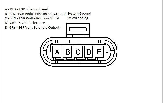
I did a WOT run and my AFR was 12.3-12.5, compared to my command AFR of 11.6. To correct this:I'm looking to hookup the PLX SM-AFR to my 03 SSEi that I can read through my PT. (I have the EGR removed.) I wanted to confirm how I could connect the WB output to the EGR connector. I understand that I can use the Pin C (BRN) wire for the WB+. Which wire could I use for the WB ground? Pin D? Pin B? I'm not a electrical engineer and don't understand the difference between Pin D and Pin B.
Here's the pinouts of the EGR connector:
Pin Wire Color Circuit No. Function
A GRY 435 EGR Solenoid Low Control
B BLK 552 Low Reference <--- WB-
C BRN 1456 EGR Valve Position Signal <--- WB+
D GRY 605 5 Volt Reference
E WHT 257 EGR Solenoid High Control
TIA
EDIT: Got it figured out. It's B. You could use D if you needed to provide 5+ volts to a sensor.
Attached is my cfg file. Under table display I log EGR Postion and two custom PIDs, AFR and AFR error. Under histogram #8 I log AFR error percentage vs MAF for 7375Hz and above. Use histogram #8 to modify the MAF to correct the AFR error. To do so, copy all cells in histogram #8. Then open your bin file, go to the MAF table, right click on the first MAF cell, click paste special and "mutliply by %", violah, the MAF between 7375Hz and 11,500Hz has been adjusted for the AFR error percentage. A few WOT runs and your actual AFR will match the AFR command.For adjusting the MAF below 7375Hz, use histogram #12. Open your bin file, go to the MAF table, right click on the first MAF cell, click paste special andand "mulitply by % - half", the MAF between 0 and 7250 Hz has been adjusted for the LTFT percentage.
edit: I'm using a PLX SM-AFR. My only complaints about the PLX is being force to use 20-22g wiring for the narrowband and EGR. The female connector provided along with the pins require thin wire (20-22g). I'm not a fan of using 20-22g wire so I used 18g and I had some trouble getting the 18g wire to fit the pins. PLX provides 1 pin with 20-22 gauge wire pre-attached, and 3 blank pins. The other concern I have about using any wideband as a narrowband is that a constant power source is required for the PLX unit. If there is no power, there is no narrowband. Currently I have the PLX unit powered by the power drop which also provides power to the aux 12V outlet and if it shorts out blowing a fuse that leaves the PLX unit with no power and no narrowband. I unplugged the PLX wideband to see if the motor would run without a narrowband and the motor kept stalling out. I may look for another power source, maybe an independent source.


 Reply With Quote