Page 1 of 2 12 LastLast
Results 1 to 20 of 30

Thread: Analog input not reading correctly

  1. #1

    Analog input not reading correctly

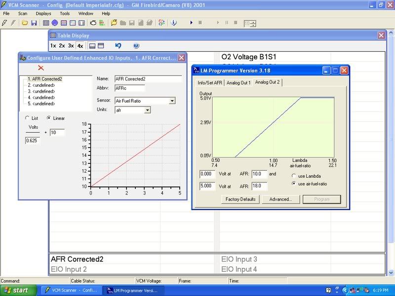
    I am working on syncing up my wideband to hp tuners. I configured my lc1 analog output to 0 volts equals 10afr and 5 volts equals 18afr. At idle the lc1 reads 14.7 and we confirmed the analog output of the lc1 reads 2.95 volts. We also confirmed the voltage at the enhanced IO pin was also 2.93 volts.

    The equation in the user configured setting for input 1 has a slope of .625 and a offset of 10. This is exactly the inverse of the lc1 output curve.

    While measuring 2.95 at the IO pin, the scanner reads 17.8 while the graph shows that it should read 14.7. Does this indicate that something is wrong with my IO box itself to give me the wrong afr?

  2. #2
    Tuner
    Join Date
    Jan 2004
    Location
    Lebanon TN
    Posts
    117
    Were you also using the ground pin on the EIO when measuring the 2.93-2.95 volts at the EIO? (that's probably not it, because you have to be getting right at the full 5v on the EIO to read 17.8)

    How many wires do you have on the EIO? Just the wideband?

  3. #3
    Potential Tuner
    Join Date
    Mar 2008
    Posts
    2
    I was working with dark-one in person today on figuring this out.

    We had two wires going to the EIO, one was the analog output from the LC1, the other was a chassis ground. We verified the chassis ground was a quality ground as well.

    Yes, when we measued the 2.95 volts, we checked the voltage across pin 1 of the EIO, to pin 5 of the EIO. I am an EFI Live user, so I'm not familiar with the EIO pin setup. Dark-One told me these are the correct pins to use for the WB02 input to the EIO, is this correct?

  4. #4
    Tuner
    Join Date
    Jan 2004
    Location
    Lebanon TN
    Posts
    117
    Yep, 1-4 are inputs, and 5-6 are ground. In an older version, 6 was a 5V source, but in the later version it's just another ground.

  5. #5
    I'm running the input in pin one and have 5 grounded to the same place as the wideband. Mine is a newer unit

  6. #6
    Tuner
    Join Date
    Jan 2004
    Location
    Lebanon TN
    Posts
    117
    It shouldn't be showing 17.8 unless it's getting almost 5 volts.

    If the voltage is definitely in the mid 2's, the ground is good, and the PID definition is definitely as shown above, then the only thing that leaves is the EIO box.


    Quote Originally Posted by dark-one
    While measuring 2.95 at the IO pin, the scanner reads 17.8 while the graph shows that it should read 14.7.
    What graph? The chart view?

    What says it should read 14.7? The commanded afr?

    How is the wideband configured on the graph/chart view? Sensor or PID?

    Can you attach a scan and the config?

  7. #7
    The graph for voltage vs. afr matchs perfectly to the one in hp tuners i made. The eio gets the correct voltage from the wideband to display 14.7. That is 2.95 volts. Hp tuners never displays the right afr though.

  8. #8
    I'm emailing hp tuners tonight. This is the second time i have had issues with my pro unit. I'll probably have to ship it back again. Can't tune my ve table without a good wideband reading

  9. #9
    HP Tuners Support
    (foff667)
    Bill@HPTuners's Avatar
    Join Date
    Jun 2004
    Location
    Hailing from Parts Unknown
    Posts
    28,261
    Please post a scanner log while logging raw voltage from your wideband.
    It doesn't have to be perfect, it just needs to be done in two weeks...

    A wise man once said "google it"

  10. #10
    Senior Tuner
    Join Date
    Nov 2002
    Location
    Central Florida
    Posts
    2,503
    You want to verify at both ends, the transfer function
    (AFR : volts) used. There's one remapping embedded in
    the WB meter and another in the "canned" HPT custom
    PID definition, and they both have to agree.

    Using LogWorks (or LM Programmer?) you should be
    able so set the output to (say) 0.50V from stop to
    stop in the wideband and see 0.50V at the EIO input
    (raw, no "custom") and then 3.50V WB and see 3.5V
    EIO. Verify the pin voltage at the EIO input with a
    meter if you don't get clean agreement and see which
    one is lying.

    LC-1 seems to b particularly susceptible to ground
    loop induced voltage errors. But I'd verify both the
    cal-curves first and then check the electricals.

  11. #11
    I get the right voltage at the io pin input. I just don't get the right afr in the program. I verified it with a multimeter. The problem lies somewhere between the io pin and what ever the software does. I'll post up some logs and what not soon. The wideband is not the problem though. I've checked it at all kinds of voltages and it is right on. My graphs for the wideband and the hp tuners match. I'll take a screenshot. How do i log the raw voltage?
    Silverstone 93 Mazda Rx-7 ls-6 swap

  12. #12
    Potential Tuner
    Join Date
    Jan 2008
    Location
    Houston, Texas
    Posts
    7
    I was about to order teh LC1 WBO...is there another one I just order that would have less problems?

  13. #13
    Again i do not feel the wideband is the issue
    Silverstone 93 Mazda Rx-7 ls-6 swap

  14. #14
    Potential Tuner
    Join Date
    Mar 2008
    Posts
    2
    Quote Originally Posted by jthomas98gs
    I was about to order teh LC1 WBO...is there another one I just order that would have less problems?
    I repeat, this is NOT A WIDEBAND ISSUE. If you cannot understand that from the information given in this thread please refrain from commenting.

  15. #15

    hey

    Maybe some of this will help


    Last edited by dark-one; 03-06-2008 at 05:50 PM.
    Silverstone 93 Mazda Rx-7 ls-6 swap

  16. #16
    I need some kind of ideas of things to try.
    Silverstone 93 Mazda Rx-7 ls-6 swap

  17. #17
    Tuner
    Join Date
    Jan 2004
    Location
    Lebanon TN
    Posts
    117
    Does the LC1 have 2 output wires like the LM1?
    I see where you programmed analog output 2.

    From the scan log, looks like hptuners saw either 0 volts, or 5 volts, the majority of the time. Except for a time in the middle where it was ranging from 0-2 volts. If during all of these times, a voltmeter is showing 2.95 (or so) externally on EIO pin #1, then it has to be something dropping/altering the signal in the EIO box...

    The EIO connector is firmly seated right?
    (just brainstorming here.)

    You may have to send it in for a checkup.


    Another testing option is to feed it a constant 2.x volts by setting up the LC1 to send a constant signal. But that will probably show the same thing you're already seeing.

  18. #18
    I watched my multimeter while i ran the log and it doesn't really match. If you set the wideband to only put out a certain voltage it will input the correct voltage. It seems that the problem does indead lie in the EIO box. I'll check over the wires but i'm certain they are well seated.
    Silverstone 93 Mazda Rx-7 ls-6 swap

  19. #19
    Tuner
    Join Date
    Jan 2004
    Location
    Lebanon TN
    Posts
    117
    What color are the analog 1 and analog 2 wires? Is it possible you are logging the analog 1 output?

    Strange that it works if you output a set voltage. That's making me think it's something on the LC-1 side, if it gets whacked only when it goes back to a programmed voltage swing.

  20. #20
    I'm using the brown wire which is output 2. I'm loging output two. What else can i check?
    Silverstone 93 Mazda Rx-7 ls-6 swap